
Fuel tank and assembling process thereof

An assembly process and fuel tank technology, applied in the automotive field, can solve problems such as damage to the common rail injector of the high-pressure fuel pump, wear of the precision moving parts of the common rail, and increased diesel impact force, so as to reduce the generation of aluminum dust and eliminate friction. , the effect of reducing friction

Active Publication Date: 2019-10-25
FAW JIEFANG AUTOMOTIVE CO
View PDF7 Cites 1 Cited by
  • Summary
  • Abstract
  • Description
  • Claims
  • Application Information

AI Technical Summary

Problems solved by technology

However, due to the large size of the diesel tank, the torsional deformation of the diesel tank along with the longitudinal beam of the vehicle is relatively large. At the same time, the impact force of the diesel oil on the inner partition of the fuel tank will also increase during driving, resulting in a relative friction between the partition and the diesel tank. Movement, the relative movement and friction between the partition and the diesel tank body will inevitably produce fine aluminum dust, which will be suspended in the diesel oil and enter the oil supply pipeline system with the diesel oil, making it easy for the aluminum dust to enter the diesel engine electronically controlled high pressure Common rail fuel injection system, the high-pressure oil pump, high-pressure fuel rail and common rail injector in the diesel engine electronically controlled high-pressure common rail fuel injection system are electronically controlled precision components. The entry of aluminum powder will cause wear of the common rail precision moving parts, and will also Cause the solenoid valve parts to stick, thus causing damage to the high-pressure oil pump, high-pressure oil rail, and common rail injector

Method used


Image

  • Fuel tank and assembling process thereof
  • Fuel tank and assembling process thereof
  • Fuel tank and assembling process thereof

Examples


Embodiment Construction

[0028] In order to make the technical problems solved by the present invention, the technical solutions adopted and the technical effects achieved clearer, the technical solutions of the present invention will be further described below in conjunction with the accompanying drawings and through specific implementation methods. It should be understood that the specific embodiments described here are only used to explain the present invention, but not to limit the present invention. In addition, it should be noted that, for the convenience of description, only the parts related to the present invention are shown in the drawings but not all of them.

[0029] In the description of the present invention, unless otherwise clearly specified and limited, the terms "connected", "connected" and "fixed" should be understood in a broad sense, for example, it can be a fixed connection, a detachable connection, or an integrated ; It can be a mechanical connection or an electrical connection;...


PUM

PropertyMeasurementUnit
thicknessaaaaaaaaaa
thicknessaaaaaaaaaa

Abstract

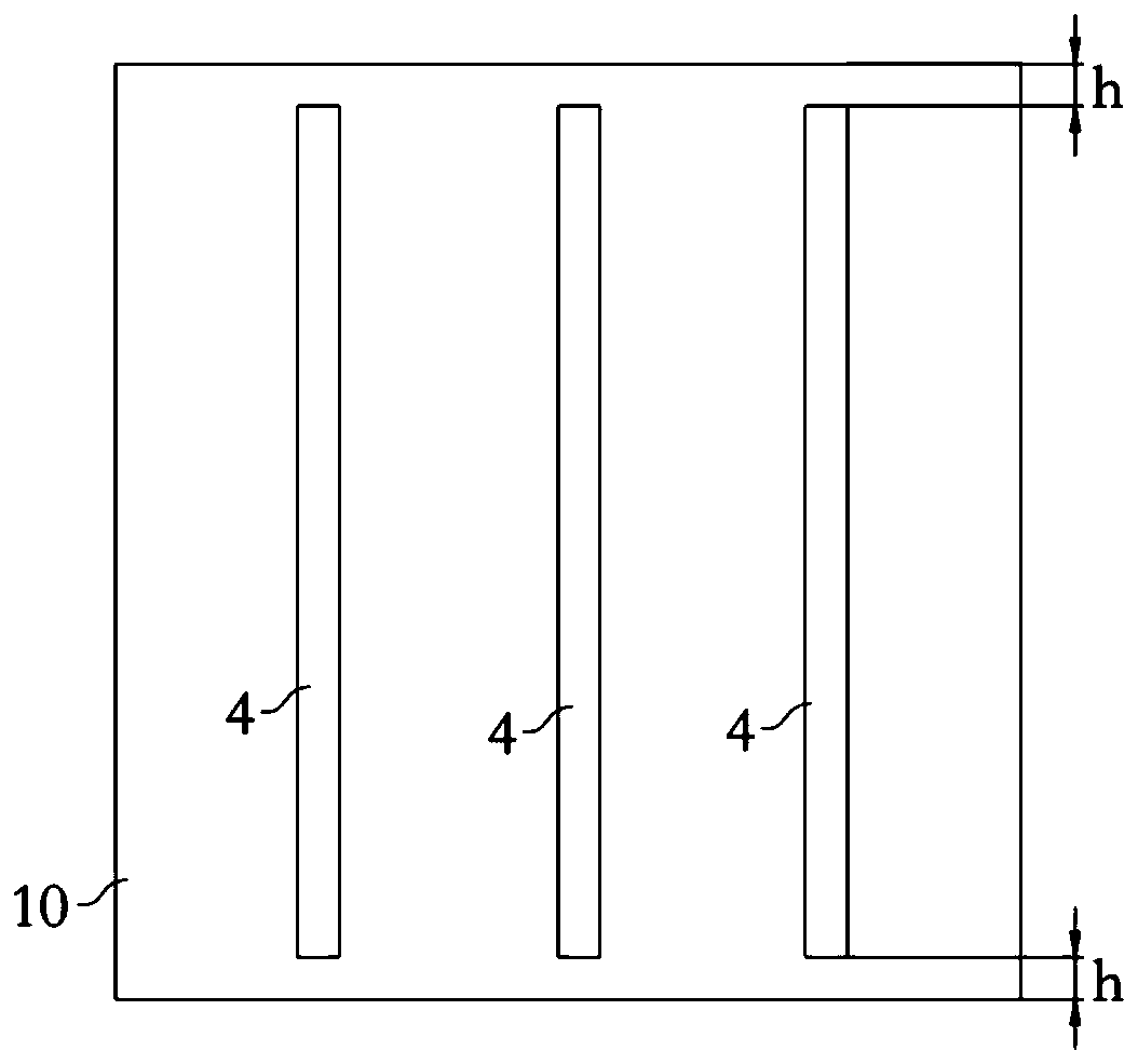
The invention discloses a fuel tank and an assembling process thereof and belongs to the technical field of automobiles. The fuel tank comprises a fuel tank body and a partition plate which is arranged in the fuel tank body; and at least one of the peripheral face of the partition plate and the annular wall face, in corresponding abutting connection with the peripheral face of the partition plate,of the fuel tank body is provided with a protective film. The assembling process of the fuel tank comprises that the protective film is pasted to the peripheral face of the partition plate and / or theannular wall face, in corresponding abutting connection with the peripheral face of the partition plate, of the fuel tank body through bonding glue. Due to the fact that at least one of the peripheral face of the partition plate and the annular wall face corresponding to the peripheral face of the partition plate is provided with the protective film, when the partition plate is installed in the fuel tank body, the protective film is arranged between the partition plate and the fuel tank, so that when the partition plate moves relative to the fuel tank body, friction between the partition plate and the fuel tank body can be reduced and even be eliminated, therefore generation of aluminum dust can be generated, and it is avoided that the aluminum dust enters a subsequent precision mechanismto damage the precision mechanism and normal running of an automobile is affected.

Description

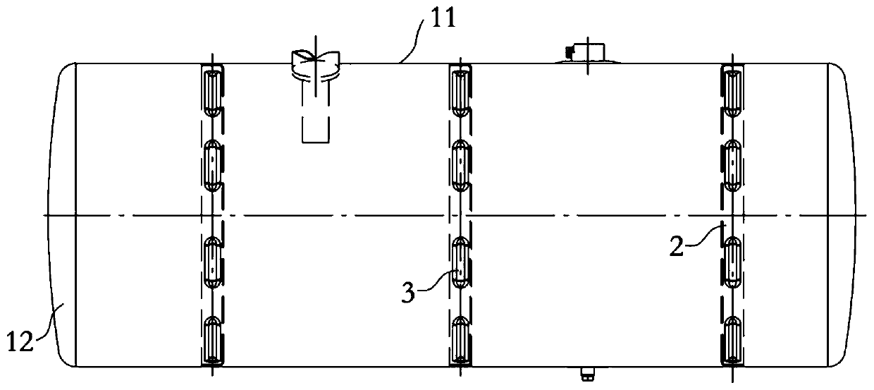
technical field [0001] The invention relates to the technical field of automobiles, in particular to a fuel tank and an assembly process thereof. Background technique [0002] At present, heavy-duty vehicles generally use large-volume aluminum alloy diesel tanks in order to ensure sufficient mileage. There are partitions installed in the tank of the diesel tank. It can improve the impact resistance of the diesel tank. However, due to the large size of the diesel tank, the torsional deformation of the diesel tank along with the longitudinal beam of the vehicle is relatively large. At the same time, the impact force of the diesel oil on the inner partition of the fuel tank will also increase during driving, resulting in a relative friction between the partition and the diesel tank. Movement, the relative movement and friction between the partition and the diesel tank body will inevitably produce fine aluminum dust, which will be suspended in the diesel oil and enter the oil s...

Claims


Application Information

Patent Timeline
Patent Type & Authority Applications(China)
IPC IPC(8): B60K15/077B29C63/02B29C63/48
CPCB29C63/02B29C63/48B60K15/077B60K2015/0777
Inventor 李冠霖戈非朱宏志贾昭远尹燕升贾旭哲张贵华韦安阳
Owner FAW JIEFANG AUTOMOTIVE CO
Learn More