
Horizontal opposed plunger pump connecting rod connecting ring

A technology of horizontally opposed and connecting rings, which is applied to variable displacement pump components, pump elements, components of pumping devices for elastic fluids, etc. and other problems, to achieve the effect of simple structure, low friction and convenient installation

Inactive Publication Date: 2019-10-25
SHANDONG JINPENG PETROCHEM EQUIP
View PDF1 Cites 2 Cited by
  • Summary
  • Abstract
  • Description
  • Claims
  • Application Information

AI Technical Summary

Problems solved by technology

[0004] However, the above-mentioned patent does not involve the detailed installation structure of the horizontally opposed plunger assembly on the crank pin of the crankshaft, but simply describes in words that the multi-row plunger assemblies are symmetrically arranged on both sides of the crankshaft, and the connecting rods of the plunger assemblies are connected to the crankshaft. How to ensure the centering installation of the connecting rod of the horizontally opposed plunger assembly relative to the crank pin, and how to improve the reliability of the connection between the connecting rod and the crank pin of the opposed plunger assembly are not involved. Mounting method on the pin, connection structure

Method used


Image

  • Horizontal opposed plunger pump connecting rod connecting ring
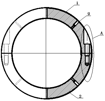
  • Horizontal opposed plunger pump connecting rod connecting ring
  • Horizontal opposed plunger pump connecting rod connecting ring

Examples


Embodiment Construction

[0021] The following will clearly and completely describe the technical solutions in the embodiments of the present invention with reference to the accompanying drawings in the embodiments of the present invention. Obviously, the described embodiments are only some, not all, embodiments of the present invention. Based on the embodiments of the present invention, all other embodiments obtained by persons of ordinary skill in the art without making creative efforts belong to the protection scope of the present invention.

[0022] see Figure 1-6 , in the embodiment of the present invention: a horizontally opposed plunger pump connecting rod connecting ring, comprising an upper semicircular connecting ring 1 and a lower semicircular connecting ring 2; the cross sections of the upper semicircular connecting ring 1 and the lower semicircular connecting ring 2 are spliced ​​together to form In the entire connecting ring, the upper semicircular connecting ring 1 is respectively provi...


PUM


Abstract

The invention discloses a horizontal opposed plunger pump connecting rod connecting ring. After being cast from an overall circular ring blank and machined and formed through an overall circular ringmachine, the overall circular ring blank is cut into an upper semicircular connecting ring and a lower semicircular connecting ring through wire cutting of a quick fed wire or a slow fed wire. The split upper semicircular connecting ring and lower semicircular connecting ring are connected into the whole connecting ring through connecting bolts or cylindrical pins with the locating function. The surface of the inner circumference of the connecting ring is coated with a wear-resistant material according to the service environment or the stress condition to form a temperature-resistant, corrosion-resistant and wear-resistance layer. A connecting ring body is provided with an outer circular oil groove, an inner circular oil groove, a lubricating oil groove and an oil lubrication hole in the radial direction or the axial direction so as to realize lubrication on a related connecting motion pair. The horizontal opposed plunger pump connecting rod connecting ring is simple in structure, lowin manufacturing cost and convenient to install, ensures the centering installation and good connecting reliability of a horizontal opposed plunger pump, improves the lubricating property and corrosion resistance of the related connecting motion pair, thereby improving the operation stability and reliability of the horizontal opposed plunger pump.

Description

technical field [0001] The invention relates to the technical field of plunger pump installation components, in particular to a horizontally opposed plunger pump connecting rod connecting ring. Background technique [0002] Existing plunger pumps are mostly arranged on one side, usually single plunger pumps or double plunger pumps, which are used in industrial fields with high pressure and large flow requirements such as oilfield water injection and steel rolling dephosphorization. Large force, large vibration and noise, etc. [0003] Based on this, the patent application number CN201810011835.5 discloses a multi-row horizontally opposed high-pressure plunger pump, which mainly includes a multi-row plunger assembly and a cylinder body. The multi-row plunger assembly is installed in the cylinder body. Rows of plunger assemblies are symmetrically arranged on both sides of the crankshaft, and the cylinder body is a split structure, separated from the centerline of the cranksha...

Claims


Application Information

Patent Timeline
Patent Type & Authority Applications(China)
IPC IPC(8): F04B53/14F04B53/22F04B53/18
CPCF04B53/14F04B53/147F04B53/18F04B53/22
Inventor 刘华洁兰俊殷富磊张智强孟晓峰孟庆军秦磊张春燕宋长山黄佳博孟令君张元法王玲玲冯烨崔汝东赵祖德
Owner SHANDONG JINPENG PETROCHEM EQUIP
Learn More