Pipe hole cutting device for simple type metal pipe fitness

A technology for cutting devices and metal pipe fittings, applied in metal processing equipment, welding equipment, plasma welding equipment, etc., can solve the problems of no economic value, high purchase cost, large floor space, etc., achieve simple structure, expand the scope of use, The effect of easy operation

Pending Publication Date: 2019-11-15
泉州职业技术大学
View PDF0 Cites 0 Cited by
  • Summary
  • Abstract
  • Description
  • Claims
  • Application Information

AI Technical Summary

Problems solved by technology

However, the existing cutting machines are complex in structure, expensive in cost, and occupy a large area. They are generally suitable for large-scale machine parts processing plants. For some occasions where a small number of holes are processed, there is no economic value in purchasing large-scale equipment, and the purchase cost is relatively high.

Method used


Image

  • Pipe hole cutting device for simple type metal pipe fitness
  • Pipe hole cutting device for simple type metal pipe fitness
  • Pipe hole cutting device for simple type metal pipe fitness

Examples


Embodiment

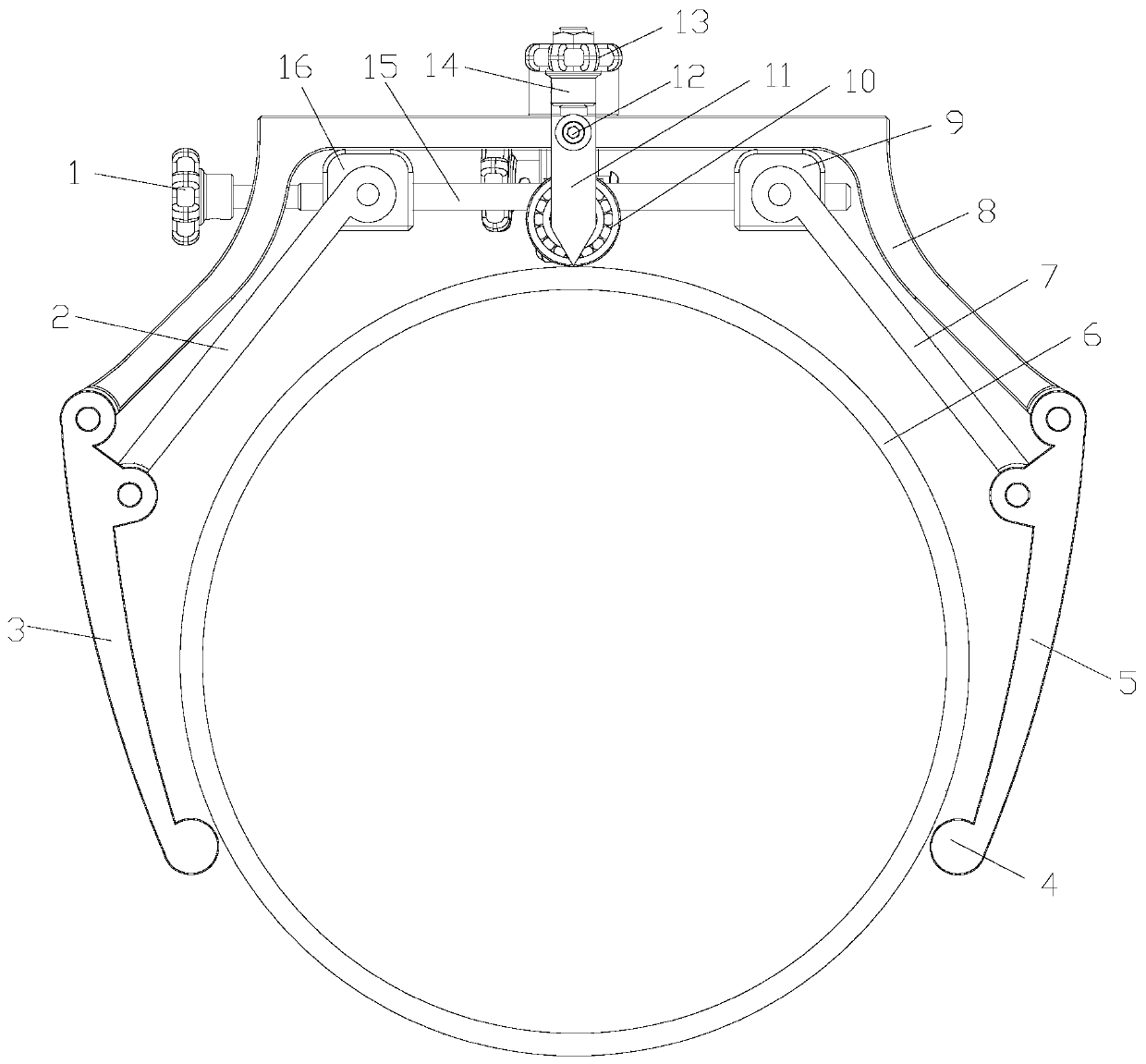
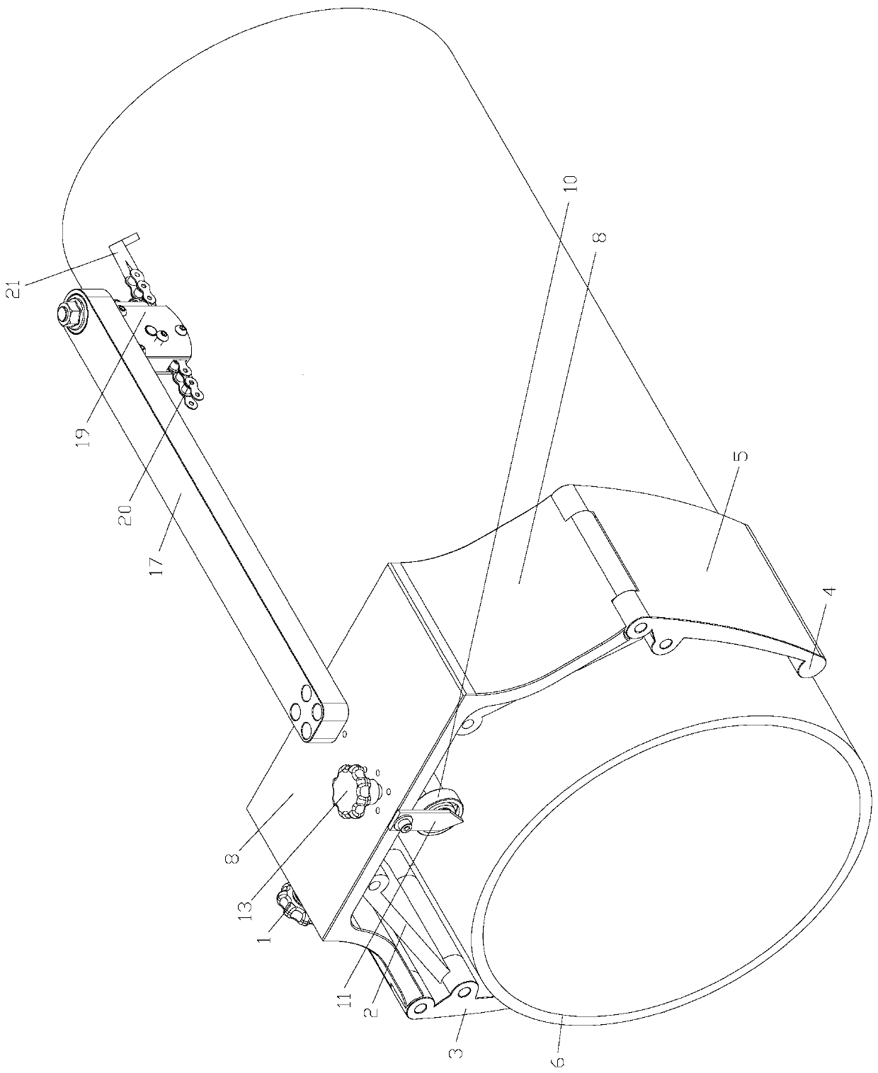
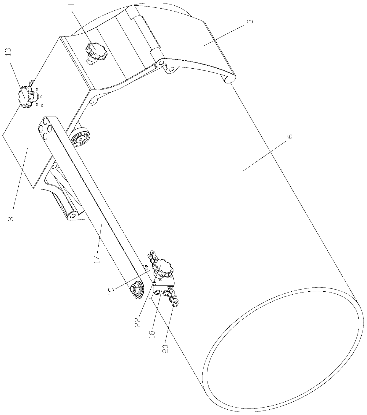
[0024] Example: such as Figure 1-3 As shown, a simple metal pipe fitting pipe hole cutting device includes a positioning device for positioning and installing a workpiece 6 and a cutting device for processing holes. The left clamping plate 3 and the right clamping plate 5 at the lower ends of the two sides of the positioning frame 8 and the left slide plate 2 and the right slide plate 9 whose lower ends are hingedly connected with the left clamping plate 3 and the right clamping plate 5 respectively, the left slide plate 2 and the right slide plate 9 The upper ends of the right slide plate 9 are all slidably mounted on the positioning frame 8, and the positioning frame 8 is provided with the upper end for driving the left slide plate 2 and the upper end of the right slide plate 9 to slide towards each other synchronously or slide backward to drive the left clamping plate 3 and the right clamping plate 5. A driving device for rotating and clamping the workpiece 6. The position...


PUM


Abstract

The invention provides a pipe hole cutting device for a simple type metal pipe fitness. The device is characterized by comprising a positioning device for positioning and mounting a workpiece and a cutting device for machining holes, wherein the positioning device comprises a N-shaped positioning frame, a left clamping plate, a right clamping plate, a left sliding plate and a right sliding plate;the left clamping plate and the right clamping plate are arranged at the lower ends of the two sides of the positioning frame in hinged mode, the lower ends of the left sliding plate and the right sliding plate are connected with the left clamping plate and the right clamping plate in hinged mode, and the upper ends of the left sliding plate and the right sliding plate are slidably arranged on thepositioning frame; the positioning frame is provided with a drive device, wherein the drive device is used for driving the upper ends of the left sliding plate and the right sliding plate to simultaneously move in the same or back direction so as to drive the left clamping plate and the right clamping plate to rotationally clamp the workpiece; and the positioning frame is provided with a mountingrod which is co-axially and parallelly with the workpiece, and the cutting device is mounted at the other end of the mounting rod. According to the pipe hole cutting device for the simple type metalpipe fitness, clamping cambered surfaces of the left clamping plate and the right clamping plate cooperate with clamping wheels so as to position and clamp the workpiece, so that the workpiece can bein centering mounting while being clamped, and therefore the device is simple in structure and convenient to operate.

Description

technical field [0001] The invention relates to the technical field of cutting equipment, in particular to a simple metal pipe hole cutting device. Background technique [0002] The development of cutting machines must meet the requirements of the development of modern machining industry. Cutting machine is divided into flame cutting machine, plasma cutting machine, laser cutting machine, water cutting and so on. Plasma cutting machine can cut all kinds of metals that are difficult to cut by oxygen cutting with different working gases, especially for non-ferrous metals, the plasma cutting speed is fast, the cutting surface is smooth, the thermal deformation is small, and there is almost no heat-affected zone. application. However, the existing cutting machines are complex in structure, expensive in cost, and occupy a large area. They are generally suitable for large-scale machine parts processing plants. For some occasions where a small number of holes are processed, there...

Claims


Application Information

Patent Timeline
Patent Type & Authority Applications(China)
IPC IPC(8): B23K10/00
CPCB23K10/00
Inventor 刘伟宝胡仟尉梁文帆吴澎东周浩然余溱
Owner 泉州职业技术大学
Why Eureka
Try Eureka