Evaporation tube structure for engine combustion chamber and engine combustion chamber structure

A technology of evaporating tube and combustion chamber, applied in combustion chamber, continuous combustion chamber, combustion method, etc., can solve the problems of great influence on product performance and quality, high maintenance cost, stress relief, etc.

Active Publication Date: 2020-07-14
NAT INST CORP OF ADDITIVE MFG XIAN
View PDF4 Cites 0 Cited by
  • Summary
  • Abstract
  • Description
  • Claims
  • Application Information

AI Technical Summary

Problems solved by technology

The evaporation tubes used in most micro-combustion chambers are straight, T or L-shaped structures, which can improve combustion efficiency to a certain extent, but the effect is poor
The other part adopts spiral tube evaporating tube and electric heating evaporating tube, but the spiral evaporating tube is easy to block, and the evaporation rate is not high, while the electric heating system is too complicated and the maintenance cost is high
The research on the structural design of the evaporation tube needs to be improved. At the same time, the welding or repair welding in the process of manufacturing and repairing the engine combustion chamber will lead to the loss of material properties. After welding or repair welding, some parts cannot be stress-relieved and restored by heat treatment. , has a great impact on product performance and quality, how to restore or enhance the weld performance has always been a difficult process problem to solve

Method used


Image

  • Evaporation tube structure for engine combustion chamber and engine combustion chamber structure
  • Evaporation tube structure for engine combustion chamber and engine combustion chamber structure
  • Evaporation tube structure for engine combustion chamber and engine combustion chamber structure

Examples


Embodiment Construction

[0034] The present invention is described in further detail below in conjunction with accompanying drawing:

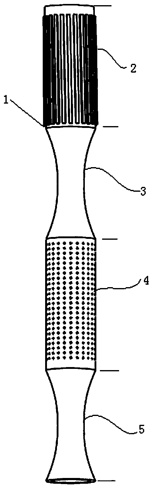
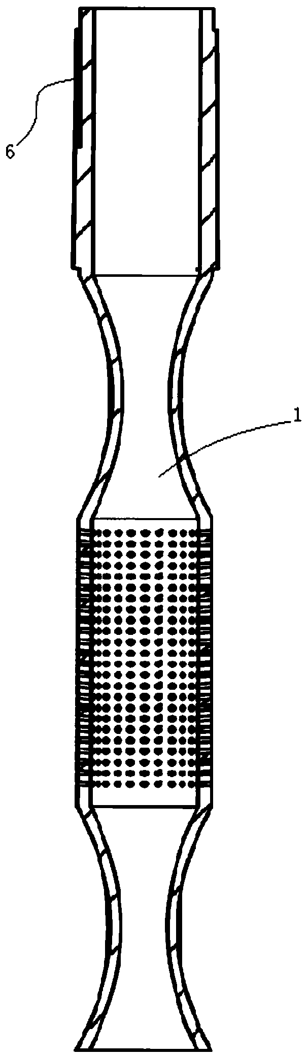
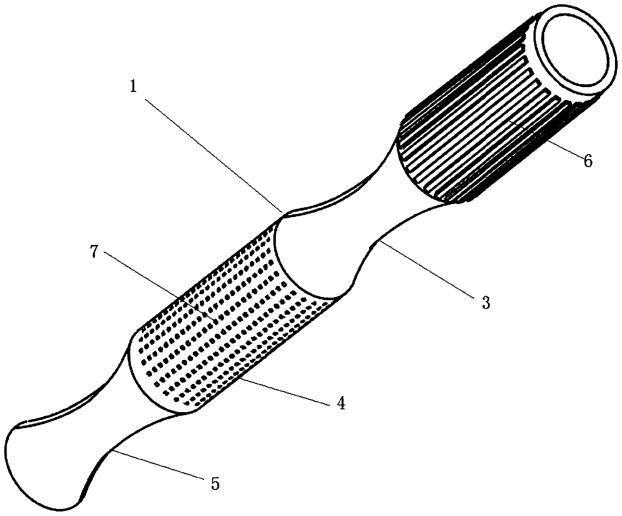
[0035] Such as Figure 1 to Figure 6 As shown, an evaporating tube structure for an engine combustion chamber includes an evaporating tube body 1, and the inner wall of the evaporating tube body 1 sequentially includes a first cylindrical section 2, a concave curved surface section 3, and a second cylindrical section from the air inlet end to the air outlet end. Section 4 and outlet section 5; the first cylindrical section 2 and the second cylindrical section 4 have the same diameter; the wall thickness of the evaporation tube body 1 is 0.3 mm to 0.6 mm;

[0036] The outer surface of the first cylindrical section 2 is provided with fins 6, the length direction of the fins 6 is arranged along the axial direction of the first cylindrical section, and a plurality of fins 6 are evenly distributed on the outer surface of the first cylindrical section 2; specifically, the fi...


PUM


Abstract

The invention discloses an evaporating pipe structure for an engine combustion chamber and an engine combustion chamber structure. An internal concave curved surface section composed of at least two cambered surfaces is utilized, two column cambered surfaces arranged symmetrically are adopted in each cambered surface, the internal concave curved surface section adopts a gradual contracting and gradual stretching structure, mixed gas flows through an evaporating pipe, a backflow area is formed in the internal concave curved surface section, the speed is reduced, the mixed space of fuel oil andair is increased, stay time in the evaporating pipe is prolonged, the contact area of the mixed gas and the wall face of the evaporating pipe is increased, and gas heat exchange is enhanced. By meansof the gradual contracting and gradual stretching curved wall face, the strong shearing effect brought by the gas enables the fuel oil and the air to be mixed more fully. Fins are arranged on the outer surface of a first cylinder section, heat exchange between high-temperature airflow in a flame cylinder and the evaporating pipe is enhanced, and the temperature in the evaporating pipe is increased. Mixing holes form oblique holes to jet flow to enable air to directly impact oil fog, atomizing evaporation of the fuel oil is promoted, the atomizing and evaporating effect of the fuel oil in the evaporating pipe is enhanced, the fuel oil is combusted fully, and emission of pollutants is reduced while the combustion efficiency is improved.

Description

technical field [0001] The invention belongs to the field of engine combustion systems, and in particular relates to an evaporation tube structure for an engine combustion chamber and an engine combustion chamber structure. Background technique [0002] A new generation of high-performance micro-engines adopting a direct-flow annular combustion chamber is the current development direction. This kind of miniature DC combustor is limited by the space layout. In terms of fuel atomization and evaporation, the evaporator tube with simple structure and low fuel supply pressure is generally used for fuel supply. Structurally, it does not have a swirler, and the atomization and evaporation of fuel depends entirely on the evaporation tube. The combustion chamber adopting the evaporation tube scheme has the advantages of simple structure, easy processing, low cost and good comprehensive combustion performance. [0003] The design of the evaporator tubes in the miniature combustor is...

Claims


Application Information

Patent Timeline
Patent Type & Authority Patents(China)
IPC IPC(8): F23R3/32
CPCF23R3/32
Inventor 张琦眭晓蔚杨红伟代赟杜璧玺程晓东卢秉恒
Owner NAT INST CORP OF ADDITIVE MFG XIAN
Why Eureka
Try Eureka