

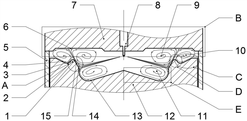
A Lip Jet Combustion System for Direct Injection Diesel Engine
A combustion system and diesel engine technology, applied in the direction of charging systems, combustion engines, mechanical equipment, etc., can solve the problems of increasing the oil-gas mixing space in the cylinder, deterioration, and increasing the oil-gas mixing space in the top gap, so as to increase the oil-gas mixing space, Improvement of air utilization rate and reduction of soot emission
- Summary
- Abstract
- Description
- Claims
- Application Information
AI Technical Summary
Problems solved by technology
Method used
Image

Examples
Embodiment Construction
[0081] The present invention will be further described below in conjunction with embodiment:
[0082] The present invention will be further described in detail below in conjunction with the accompanying drawings and embodiments. It should be understood that the specific embodiments described here are only used to explain the present invention, but not to limit the present invention. In addition, it should be noted that, for the convenience of description, only some structures related to the present invention are shown in the drawings but not all structures.
[0083] It should be noted that like numerals and letters denote similar items in the following figures, therefore, once an item is defined in one figure, it does not require further definition and explanation in subsequent figures. Meanwhile, in the description of the present invention, the terms "first", "second", etc. are only used to distinguish descriptions, and cannot be understood as indicating or implying relative...
PUM
 Abstract
Description
Claims
Application Information