
A radiant air conditioning system

A technology of radiant air conditioning and radiant ceiling, applied in the field of indoor air conditioning, can solve problems such as poor air quality, affecting thermal energy radiation efficiency, discomfort, etc., to improve heating or cooling capacity, improve thermal energy radiation efficiency, and improve the quality of living environment Effect

Active Publication Date: 2021-11-26
江苏碳元舒适加建筑科技有限公司
View PDF15 Cites 0 Cited by
  • Summary
  • Abstract
  • Description
  • Claims
  • Application Information

AI Technical Summary

Problems solved by technology

[0002] At present, there are two main problems in the traditional air-conditioning system: one is high energy consumption; the other is that the air quality in the indoor environment is relatively poor, which is easy to cause people's discomfort
Compared with traditional air conditioners, the radiant ceiling technology can effectively reduce the wind speed and vertical temperature gradient, and greatly improve the comfort of indoor occupants. However, because radiant air conditioners are surface cooling methods, the cooling surface is in direct contact with the environment, which leads to summer room The hot and humid air inside encounters the radiant panel with a lower temperature, and it is easy to condense into water droplets on the surface of the radiant panel. Therefore, not only the heating and cooling capabilities of the radiant air conditioner are the main technical difficulties, but also how to solve the problem of condensation is currently Main Technical Difficulties
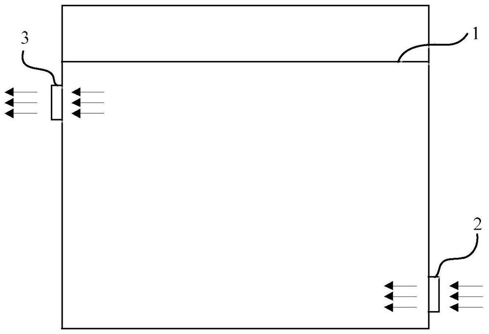
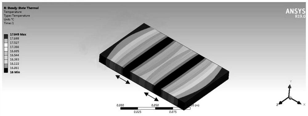
[0005] The main direction to overcome the technical difficulties: 1. Combine the radiant ceiling with the fresh air system to speed up the heat energy diffusion rate radiated from the radiant ceiling; 2. Improve the radiation efficiency of the radiant ceiling. figure 2 As shown, when heating or heating, the pipeline 20 transfers the heat energy in the pipeline to the outside. In the actual application process, we found that in the width direction of the plate body 10, the heat energy first radiates parallel to the width direction of the plate body 10 Then gradually radiate in the width direction of the vertical plate body 10, such as figure 1 Indicated by the direction of the arrow in , this makes the heat loss we need to radiate in the width direction of the vertical plate body 10 very large (for example, the water temperature in the pipeline 20 is 30°C, and the temperature coming out of the radiating surface is only 26°C), which greatly affects The heat radiation efficiency is improved, and the heat energy radiates to the room for a long time

Method used


Image

  • A radiant air conditioning system
  • A radiant air conditioning system
  • A radiant air conditioning system

Examples


Embodiment 1

[0034] Such as figure 1 As shown, this embodiment 1 provides a radiant air conditioning system, including: a control unit, a fresh air device connected to the control unit, a dehumidifier and a radiant ceiling unit 1; The air outlet 2 is connected, and the other end of the air inlet pipe is connected with the dehumidification device; the air outlet pipe of the fresh air device is connected with the indoor air outlet 3; the air outlet 3 is located above and close to the radiant ceiling unit 1; and the The air inlet 2 is located below and close to the ground.

[0035] Specifically, the radiant air-conditioning system of this embodiment dehumidifies the outdoor fresh air through the dehumidification device, and the outdoor fresh air after the dehumidification treatment enters the room through the fresh air device, which solves the problem that the radiant ceiling unit 1 is prone to radiating heat when the radiant ceiling unit 1 is cooling. At the same time, this fresh air devic...

Embodiment approach

[0055] There are two raised parts 10, and R=5mm, J1=J2=1.5mm, then H=13mm, L=3mm, A=30mm, B=20mm, therefore, a=10mm; b=46mm; E = 5.7143 mm.

[0056] All in all, this graphite plate changes the existing flat structure into a mountain-shaped structure, which optimizes the heat transfer path, so that the heat energy transmitted by the pipeline can be transferred to the bottom of the peak with high efficiency and low loss, thereby improving the heat radiation of this graphite plate It also effectively shortens the time for heat energy to radiate into the room; at the same time, compared with the existing flat structure, the materials used in the graphite plate with the peak-shaped structure are greatly reduced under the condition that the density of the graphite material is equal, thereby reducing The manufacturing cost is reduced, so the graphite plate has great economic benefits.

[0057] To sum up, this radiant air conditioning system dehumidifies the outdoor fresh air through...


PUM


Abstract

The invention relates to a radiant air conditioning system, comprising: a control unit, a fresh air device connected to the control unit, a dehumidification device and a radiant ceiling unit; It is connected with the dehumidification device; the air outlet pipe of the fresh air device is connected with the indoor air outlet; the air outlet is located above and close to the radiant ceiling unit; and the air inlet is located below and close to the ground; the radiant air conditioner of the present invention The system dehumidifies the outdoor fresh air through the dehumidification device. After the dehumidification treatment, the outdoor fresh air enters the room through the fresh air device, which solves the problem of dew condensation on the radiation surface of the radiant ceiling unit when cooling; at the same time, the fresh air device Combined with the ground-in and top-out air supply mode, it can better replace indoor dirty air, thereby improving the quality of the indoor living environment.

Description

technical field [0001] The invention belongs to the technical field of indoor air conditioning, and in particular relates to a radiation air conditioning system. Background technique [0002] At present, there are two main problems in the traditional air-conditioning system: one is high energy consumption; the other is that the air quality in the indoor environment is relatively poor, which easily causes people's discomfort. [0003] With the continuous improvement of the quality of life, people are no longer simply satisfied with the current air-conditioning system to provide only suitable temperature and humidity, but to develop more comfortable, healthy, energy-saving and low-carbon requirements on this basis. Especially under the current serious air pollution, people have put forward more urgent requirements for the improvement of the air quality of the indoor environment. [0004] In this context, the radiant ceiling technology has come into people's field of vision an...

Claims


Application Information

Patent Timeline
Patent Type & Authority Patents(China)
IPC IPC(8): F24F5/00F24F3/14F24F7/04F24F11/89
CPCF24F5/0092F24F3/14F24F7/04F24F11/89F24F13/22F24F2013/221
Inventor 徐世中周海翔陶则超李禹
Owner 江苏碳元舒适加建筑科技有限公司
Learn More