Die-cutting lamination system and method

A lamination and cutting technology, applied in electrochemical generators, electrical components, climate sustainability, etc., can solve the problem that the speed of lamination cannot be substantially improved, reduce the speed of manipulator feeding, maintenance costs, energy consumption, etc. Problems such as large consumption, to achieve the effect of reducing the risk of diaphragm folds and outer drain electrodes, small space occupancy, and breaking through the limitations of mechanical structures

Active Publication Date: 2019-10-25
SVOLT ENERGY TECHNOLOGY CO LTD
View PDF8 Cites 18 Cited by
  • Summary
  • Abstract
  • Description
  • Claims
  • Application Information

AI Technical Summary

Problems solved by technology

[0003] At present, most of them use the z-type lamination process, but the world’s fastest lamination speed that has been mass-produced is 0.6s / piece. This lamination method is relatively slow, resulting in a large demand for equipment, a large footprint, and high purchase costs. , later maintenance cost and energy consumption are large
There are two main reasons for the slow lamination speed: one is that the laminations are loaded by magazines, and there will be double sheet suction during the feeding process. Therefore, the traditional lamination opportunities include blowing, brushing, shaking, double Devices such as sheet detection are used to prevent double-sheet suction. At present, no matter what method is used, the double-sheet problem cannot be completely eliminated, and these devices have greatly reduced the speed of manipulator feeding; second, the traditional lamination method is first. Stack the negative electrode, then wrap the diaphragm on the negative electrode, then stack the positive electrode, and then wrap the diaphragm on the positive electrode. The stacking unit of this stacking method is a single pole piece or a single diaphragm. Due to the limitation of the mechanical structure, the stacking speed cannot be realized. Substantial improvement

Method used


Image

  • Die-cutting lamination system and method
  • Die-cutting lamination system and method
  • Die-cutting lamination system and method

Examples


Embodiment Construction

[0037] It should be noted that, in the case of no conflict, the embodiments of the present invention and the features in the embodiments can be combined with each other.

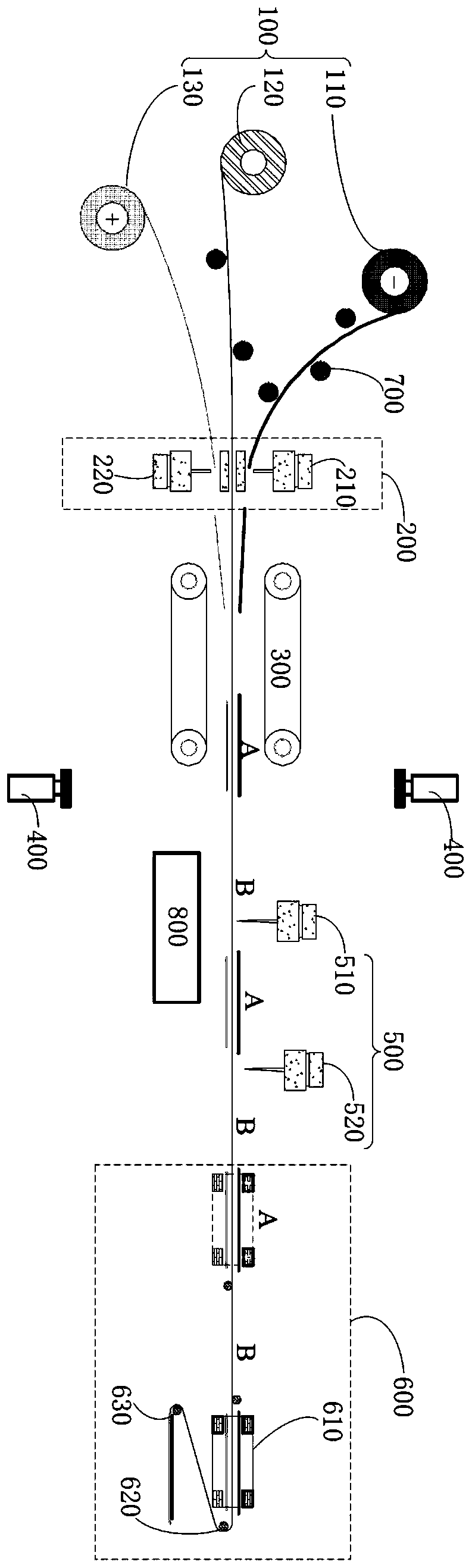
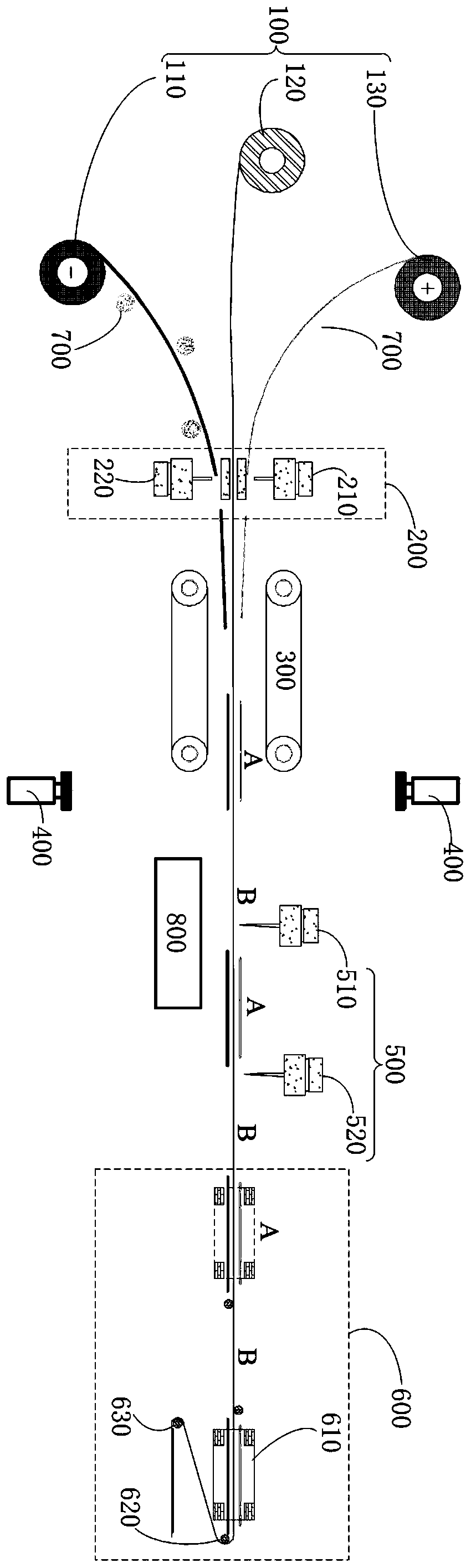
[0038]According to a first aspect of the invention, the invention proposes a die-cut lamination system. According to an embodiment of the present invention, such as figure 1 or figure 2 As shown, the system includes: an unwinding mechanism 100 , a pole roll cutting mechanism 200 , a preheating rolling device 300 , a detection device 400 , a diaphragm cutting mechanism 500 and a stacking device 600 .

[0039] The following will refer to the attached Figure 1-7 The above-mentioned die-cut lamination system will be described in detail in conjunction with the embodiments.

[0040] Unwinding mechanism 100 and pole roll cutting mechanism 200

[0041] According to an embodiment of the present invention, the unwinding mechanism 100 includes a negative electrode unwinding mechanism 110, a diaphragm unwinding me...


PUM


Abstract

The invention provides a die-cutting lamination system and method. The system comprises an unwinding mechanism, a pole roll cutting mechanism, a preheating rolling device, a detection device, a diaphragm cutting mechanism and a lamination device, and is characterized in that a negative pole cutting mechanism is matched with a negative pole unwinding mechanism and cuts a negative pole piece, a positive pole cutting mechanism is matched with a positive pole unwinding mechanism and cuts a positive pole piece, and the lamination of the negative pole piece and the positive pole piece on the upper and lower sides of a diaphragm is obtained; the preheating rolling device enables the positive pole piece and the negative pole piece of the lamination to be adhered to the diaphragm; the detection device detects whether the lamination has a defect or not; a first diaphragm cutting mechanism cuts and discharges defective lamination units in pairs, a second diaphragm cutting mechanism carries out diaphragm cutting on the last qualified lamination unit based on the number of layers of the lamination; and the lamination device enables the positive and negative pole lamination units and diaphragm lamination units to be alternately laminated. The system has the advantages of relatively simple structure, high lamination speed, low failure rate, small number of diaphragm cutting times of the system and low risk of exposing pole pieces by diaphragm folds.

Description

technical field [0001] The invention relates to the technical field of batteries, in particular to a die-cut lamination system and method. Background technique [0002] In the environment of the automobile industry using traditional energy as power supply, the problem of environmental pollution has aroused people's attention to environmental protection and resource utilization. Actively developing new energy vehicles and realizing the electrification of the automobile industry is a strategic measure to achieve the goal of "overtaking on curves" in foreign automobile industries. Lithium-ion device technology is a key technology for the development of electric vehicles. The square lamination technology is one of the most advanced lithium-ion battery manufacturing technologies at present. Among them, the lamination speed directly determines the production capacity of the whole line and the manufacturing cost of the battery cell. [0003] At present, most of them use the z-typ...

Claims


Application Information

Patent Timeline
Patent Type & Authority Applications(China)
IPC IPC(8): H01M10/0583
CPCH01M10/0583Y02E60/10Y02P70/50H01M10/0463H01M10/0404H01M50/46H01M4/0435H01M10/0459
Inventor 郑赫金正贤赵凯金省周滕立杰徐春龙王洋
Owner SVOLT ENERGY TECHNOLOGY CO LTD
Why Eureka
Try Eureka