Binocular camera device with front light splitting structure

A technology of binocular camera and beam splitting device, which is applied in the field of cameras, can solve the problem of insufficient back focus space of the lens, and achieve the effects of reducing work links, increasing degrees of freedom, and increasing costs

Pending Publication Date: 2019-10-25
GANSU ZHICHENG NETWORK TECH CO LTD +1
View PDF0 Cites 4 Cited by
  • Summary
  • Abstract
  • Description
  • Claims
  • Application Information

AI Technical Summary

Problems solved by technology

[0004] The technical problem to be solved by the present invention is to provide a binocular imaging device with a pre-light splitting structure that effectively solves the problem of insufficient back focus space of the lens

Method used


Image

  • Binocular camera device with front light splitting structure
  • Binocular camera device with front light splitting structure
  • Binocular camera device with front light splitting structure

Examples


Embodiment 1

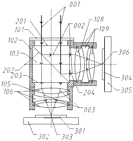
[0024] Example 1 as figure 2 As shown, the rear of the spectroscopic device 103 is provided with a first imaging lens group 106, and its side is provided with a second imaging lens group 109, which are used to focus and project the two beams of sub-rays after the incident light 001 has been split by the spectroscopic device 103 respectively. On the first optical sensor 301 and the second optical sensor 304, the two beams of sub-rays are reflected light and transmitted light respectively.

[0025] The forward light window 101 uses high-transmittance optical glass as the incident light window, and the surface is coated with an anti-reflection film to enhance light transmittance; a high-hardness protective film is coated to prevent scratches on the surface of the lens. The thickness is designed to be 1-3 mm, and the area is guaranteed to completely cover the incident surface 201 of the spectroscopic device 103 . The mechanical housing 102 has a built-in gasket 112, and the mech...

Embodiment 2

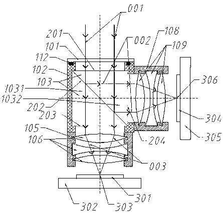
[0030] Example 2 as image 3 As shown, the rear of the spectroscopic device 103 is provided with a first imaging lens group 106 and a second imaging lens group 109, which are used to focus and project the two beams of sub-rays after the incident light 001 is split by the spectroscopic device 103 onto the first optical sensor respectively. 301 and the second optical sensor 304.

[0031] The beam splitting device 103 adopts a broadband non-polarizing cubic beam splitting prism mirror, and its working wavelength is 400nm~1100nm. Its structure is the same as that of Embodiment 1. It is formed by glueing a right-angle sub-prism I1031 and a right-angle sub-prism II1032, and the glued surface 202 is coated with a functional film to realize the light-splitting function. . The incident surface 201, the first exit surface 203, and the second exit surface 204 are the same as in Embodiment 1. Since the reflected light of the film generally produces polarized light, an additionally design...

Embodiment 3

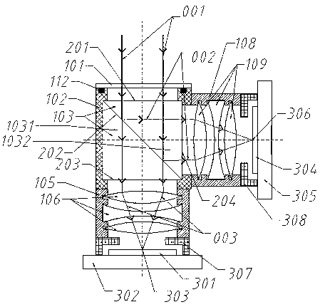
[0035] Embodiment 3 The spectroscopic device 103 includes a spectroscopic prism, and the spectroscopic prism is formed by cementing a triangular sub-prism and an offset sub-prism. A day / night switch is provided between the first imaging lens group 106 , the second imaging lens group 109 , the first optical sensor 301 , and the second optical sensor 304 . The day / night converter includes a long-wave cut filter.

[0036] Considering that light is reflected from the coating surface, linearly polarized light will inevitably be generated, resulting in different polarization components of transmitted light and reflected light. This effect can be reduced by optimizing the film structure, but it cannot be avoided. Sometimes, however, polarized light is useful. Therefore, in this embodiment, the main purpose is to realize polarization and spectroscopic imaging of light.

[0037] like Figure 4 As shown, the overall structural design and composition are similar to those of Example 2....


PUM


Abstract

The invention relates to a binocular camera device with a front light splitting structure, which comprises a mechanical shell, and a front light inlet window, a light splitting device, a first opticalsensor and a second optical sensor which are positioned at one end of the mechanical shell, and is characterized in that the light splitting device is positioned behind the front light inlet window;and a first imaging lens group and a second imaging lens group are also arranged in the mechanical shell. Through ingenious design, the light splitting device is arranged in front, the problem that the back focus space of the lens is not enough is solved, a light splitting structure can be completed on the basis of not changing functions and performance of an existing lens, and design and manufacturing of the binocular camera are completed.

Description

technical field [0001] The invention relates to the field of cameras, in particular to a binocular camera device with a front light splitting structure. Background technique [0002] At present, the camera devices that appear most on the market are monocular camera devices based on a single camera. A lens is matched with an optical sensor, which works in a fixed spectral band to form an optical-based image acquisition camera. However, as image acquisition equipment is more and more widely used, the limitations of traditional monocular camera devices are getting bigger and bigger. As a result, binocular or even multi-eye cameras were invented. These multi-eye cameras have better performance than monocular cameras and a wider range of applications, such as optical measurement, panoramic cameras, space modeling, high-speed capture, multi-spectral imaging, etc. [0003] Usually, the lenses of a multi-camera are spatially independent of each other, and each lens is imaged inde...

Claims


Application Information

Patent Timeline
Patent Type & Authority Applications(China)
IPC IPC(8): H04N5/225G02B27/12
CPCG02B27/126H04N23/55H04N23/45
Inventor 邓剑波倪显见邓弘王振华
Owner GANSU ZHICHENG NETWORK TECH CO LTD
Why Eureka
Try Eureka