Vacuum pump and vane parts and rotor for the vacuum pump and fixed vanes

A vacuum pump and vane technology, which is applied to parts, pump elements, pumps, etc. of elastic fluid pumping devices, can solve problems such as flashing, increased processing costs, and increased curvature of convex arc surfaces, so as to prevent backflow , the effect of preventing pollution

Active Publication Date: 2022-01-14
EDWARDS JAPAN
View PDF8 Cites 0 Cited by
  • Summary
  • Abstract
  • Description
  • Claims
  • Application Information

AI Technical Summary

Problems solved by technology

However, according to such a structure, since the angle formed by the surface of the upper end 7A of the rotary blade 7 and the surface (chamfered surface) of the chamfered portion MS is an acute angle, burrs caused by machining are likely to occur, and the processing cost increases. The bluntness of the machined edge produced during machining and the increase in the curvature of the convex arc surface caused by the aforementioned plating have the opposite effect of increasing the proportion of particles that flow back.

Method used


Image

  • Vacuum pump and vane parts and rotor for the vacuum pump and fixed vanes
  • Vacuum pump and vane parts and rotor for the vacuum pump and fixed vanes
  • Vacuum pump and vane parts and rotor for the vacuum pump and fixed vanes

Examples


Embodiment Construction

[0066] Hereinafter, the best mode for carrying out the present invention will be described in detail with reference to the drawings. In the present embodiment, as an example of a vacuum pump, a so-called compound vane type turbomolecular pump including a turbomolecular pump unit composed of a plurality of exhaust layers and a screw groove exhaust layer is used as an exhaust mechanism. In addition, this embodiment can also be applied to a pump having only a turbomolecular pump unit.

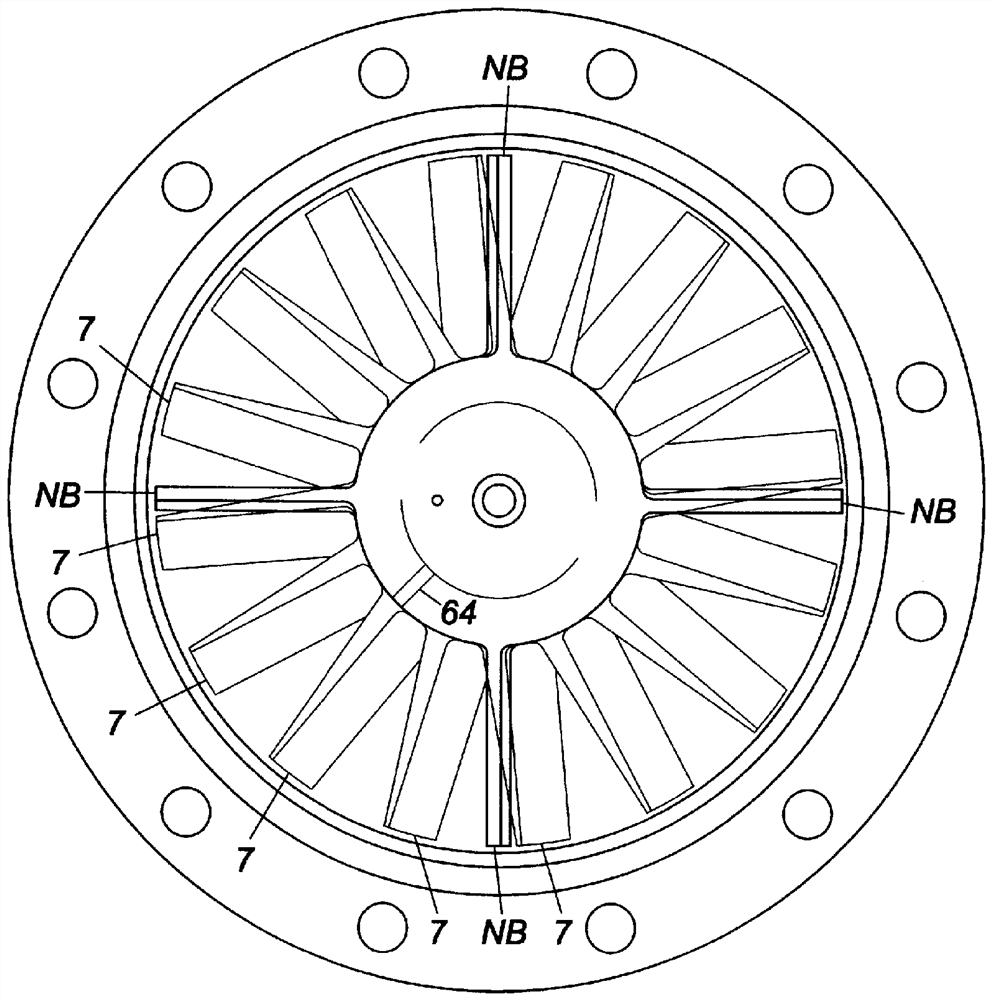
[0067] figure 1 It is a cross-sectional view of a vacuum pump to which the present invention is applied.

[0068] If refer to figure 1 , the vacuum pump P1 in the figure includes an outer case 1 having a cylindrical cross-section, a rotor 6 arranged in the outer case 1 , a support mechanism for rotatably supporting the rotor 6 , and a drive mechanism for rotationally driving the rotor 6 .

[0069] The outer casing 1 has a bottomed cylindrical shape in which a cylindrical pump casing 1A and a ...


PUM


Abstract

The invention provides a vacuum pump, a blade part and a rotor used in the vacuum pump, and a fixed blade, which can effectively prevent the backflow of particles from the vacuum pump to the vacuum chamber without damaging the gas molecule discharge performance of the vacuum pump, and are suitable for preventing Contamination in the vacuum chamber due to backflow of particles. The vacuum pump has multiple exhaust layers (PT) that function as a mechanism for discharging gas molecules from the suction port to the exhaust port, and the uppermost exhaust layer among the multiple exhaust layers (PT) Between (PT (PT1)) and the suction port, as a particle transfer layer that transfers particles along the exhaust direction of gas molecules, it is equipped with rotating blades (7 (71, 75) constituting the uppermost exhaust layer (PT1) ) rotate together and have a smaller number of blades (NB) than the number of rotating blades ( 7 ) constituting the uppermost exhaust layer ( PT1 ).

Description

technical field [0001] The present invention relates to a vacuum pump used as a gas discharge mechanism in a processing chamber of a semiconductor manufacturing device, a flat panel display manufacturing device, a solar panel manufacturing device, and other vacuum chambers, and is particularly suitable for efficiently discharging gas molecules without impairing the gas molecule discharge performance of the vacuum pump. A vacuum pump that prevents backflow of particles (particles) from the vacuum pump to the chamber to prevent contamination of the chamber by the backflow of particles. Background technique [0002] Vacuum pumps such as turbomolecular pumps and screw groove pumps are mostly used for exhausting vacuum chambers that require high vacuum. Figure 18 It is a schematic diagram of an exhaust system using a conventional vacuum pump as the gas exhaust mechanism of the vacuum chamber, Figure 19 (a) in the Figure 18 The uppermost exhaust layer of the conventional vacuum...

Claims


Application Information

Patent Timeline
Patent Type & Authority Patents(China)
IPC IPC(8): F04D19/04
CPCF04D19/042F04D29/324F05D2240/303F04D29/701F05D2220/3217F05D2240/306F05D2250/70F05D2260/607F05D2210/12F04D19/04F05B2240/30
Inventor 野中学江野泽秀树
Owner EDWARDS JAPAN
Why Eureka
Try Eureka