
Construction process for indoor drainage ditch

A construction technique and drainage ditch technology, which is applied in waterway systems, water supply devices, sewer pipe systems, etc., can solve problems such as difficulty in ensuring straightness of ditch boundaries, displacement of formwork, and difficulty in determining clearance dimensions, etc.

Inactive Publication Date: 2019-10-29
CHINA METALLURGICAL CONSTR ENG GRP
View PDF12 Cites 0 Cited by
  • Summary
  • Abstract
  • Description
  • Claims
  • Application Information

AI Technical Summary

Problems solved by technology

Using the above-mentioned construction technology, there are the following problems: Construction difficulties and disadvantages: 1. During concrete construction, it is necessary to use wooden squares or formwork on both sides of the ditch for boundary isolation. Since the formwork itself is light in weight and not easy to fix, it is difficult to install it on the floor. During the construction process, due to the lateral pressure of the concrete, it is easy to cause the formwork to shift, and it is often difficult to ensure the straightness of the ditch boundary after the formwork is removed; Floor spring line on both sides of the ditch, trimming
3. After the above process, when the cover plate is finally put on hold, due to the error in the processing size of the cover plate, the gap between the cover plate and the concrete surface layer will be larger in some positions, and smaller in some places, which will affect the sensory effect
At the same time, the irregular size of the cover plate will also bring difficulties to determine the headroom size when the thread is stretched.
[0003] The following problems will exist when using secondary construction to trim the boundary: (1) It is difficult to ensure the firmness of the combination of new and old concrete at the pouring place. Over time, for the ditch at the driving position, it will be caused by external dynamic loads. The joint breaks, resulting in later rework
(2) Due to the small area of ​​the post-poured concrete, it is not convenient to use large machinery to polish the wear-resistant floor as in large-area construction. Therefore, the wear-resistant floor at this part often cannot be re-constructed
(1) First of all, due to manual operation during cutting, it is difficult to ensure the straightness of partial cutting
(2) Secondly, chiseling is required after cutting. Chiseling will cause the edge line to be uneven and straight, and the edge line needs to be repaired again

Method used


Image

  • Construction process for indoor drainage ditch

Examples


Embodiment

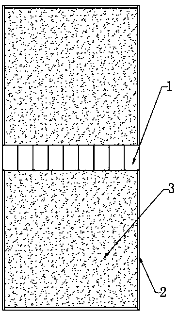
[0020] The indoor drainage ditch construction technology provided in this embodiment includes the following steps: S1, pre-preparation, preparing formwork of corresponding size and quantity, setting-out tools, excavation equipment and concrete mixing device, and at the same time, prefabricating steel pipes in the factory according to design standards Mixed structure ditch cover 1; S2, according to the design requirements, measuring and setting out at the construction position of the drainage ditch, and springing or pulling two thin lines according to the design width of the ditch when setting out; Within the construction range of the ditch, excavate several deep pits at intervals, and place multiple stakes at intervals in each deep pit, the height of the stakes is the sum of the design elevation of the ditch and the cushion layer; S4, earthwork excavation , using excavation equipment to excavate the earth within the construction range of the ditch formed after setting out the l...


PUM

PropertyMeasurementUnit
Thicknessaaaaaaaaaa

Abstract

The invention discloses a construction process for an indoor drainage ditch. The construction process comprises the following steps that S1, early-stage preparation is made; S2, surveying and setting-out operation is conducted; S3, a plurality of stakes are placed within a ditch construction range formed in the setting-out position of the drainage ditch at intervals, and the height of the stakes is the sum of the ditch designed elevation and a cushion layer; S4, earth is excavated, and a ditch foundation trench is formed after excavation; S5, the stakes are taken out, and pouring of the ditchcushion layer and the ditch wall is conducted sequentially; S6, precast ditch cover plates are put on the ditch wall one by one, and adjacent ditch cover plates need to be attached during putting; S7, templates are arranged on the side of the ditch, a built template frame and the side ends of all the ditch cover plates form a sealed concrete pouring template frame together, then sand concrete ispoured into the concrete pouring template frame, and a concrete surface layer is formed; and S8, the templates are removed, and the surface layer is maintained. The construction process for the indoordrainage ditch is small in construction difficulty and high in forming quality, and the boundary of the surface layer is good in flatness after construction.

Description

technical field [0001] The invention relates to a drainage ditch construction technology, in particular to an indoor drainage ditch construction technology. Background technique [0002] At present, the construction process of the indoor drainage ditch is as follows: measurement, setting out → earthwork excavation → pouring cushion, ditch wall, fine stone concrete surface and wear-resistant layer in sequence → springing the line on the ground on both sides of the ditch, and Trimming the concrete surface layer → laying down the reinforced concrete prefabricated trench cover. Using the above-mentioned construction technology, there are the following problems: Construction difficulties and disadvantages: 1. During concrete construction, it is necessary to use wooden squares or formwork on both sides of the ditch for boundary isolation. Since the formwork itself is light in weight and not easy to fix, it is difficult to install it on the floor. During the construction process, ...

Claims


Application Information

Patent Timeline
IPC IPC(8): E03F3/04E03F3/06
CPCE03F3/046E03F3/06
Inventor 刘新易家伟柏春龙李倩
Owner CHINA METALLURGICAL CONSTR ENG GRP
Learn More