
Multi-sound-cavity telephone receiver

A receiver and sound cavity technology, applied in the field of multi-sound cavity receivers, can solve problems such as poor low-frequency sound wave characteristics, and achieve the effect of reducing waste

Pending Publication Date: 2019-10-29
SUZHOU YICHUAN TECH CO LTD
View PDF1 Cites 0 Cited by
  • Summary
  • Abstract
  • Description
  • Claims
  • Application Information

AI Technical Summary

Problems solved by technology

[0006] Therefore, the technical problem to be solved by the present invention is that the existing receiver has only one sound cavity, and the characteristics of processing low-frequency sound waves are relatively poor.

Method used


Image

  • Multi-sound-cavity telephone receiver
  • Multi-sound-cavity telephone receiver
  • Multi-sound-cavity telephone receiver

Examples


Embodiment 1

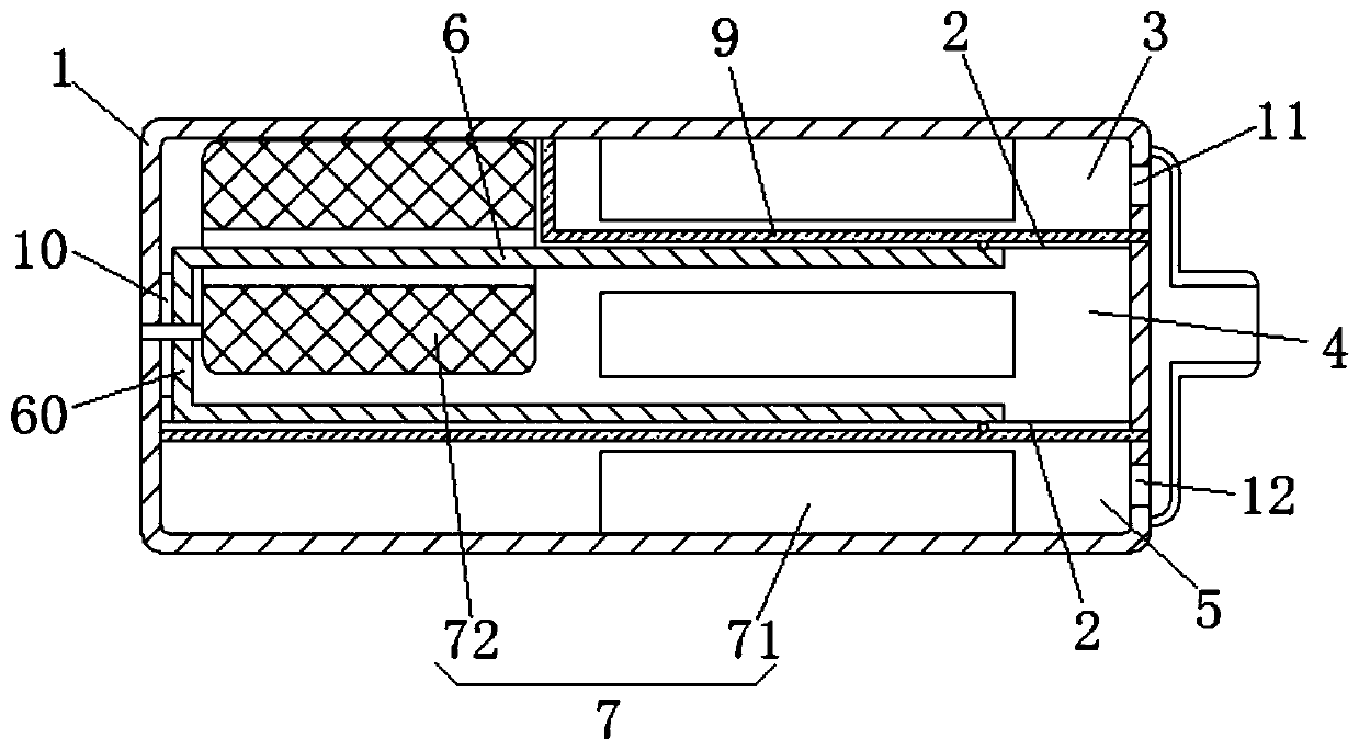
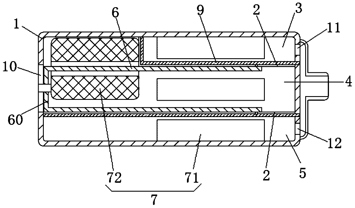
[0048] This embodiment provides a multi-cavity receiver, which includes a housing 1, a sounding membrane mechanism and at least one driving mechanism. Wherein, the pronunciation membrane mechanism comprises at least two pronunciation membranes 2, is installed on the casing 1, as figure 1 As shown, two sounding membranes 2 are set, and the two sounding membranes 2 divide the hollow cavity into a main sound cavity 3, an installation cavity 4 and a secondary sound cavity 5, and the main sound cavity 3, the installation cavity 4 and the secondary sound cavity 5 Arranged side by side, the volumes of the main sound cavity 3 and the secondary sound cavity 5 are not equal, the pronunciation membrane 2 of the main sound cavity 3 is L-shaped, and a support frame 9 is also arranged in the hollow cavity, such as Figure 5As shown, the supporting frame 9 is L-shaped as a whole, and the sounding film 2 of the main sound cavity 3 is bonded and fixed on the wall surface of the supporting fram...

Embodiment 2

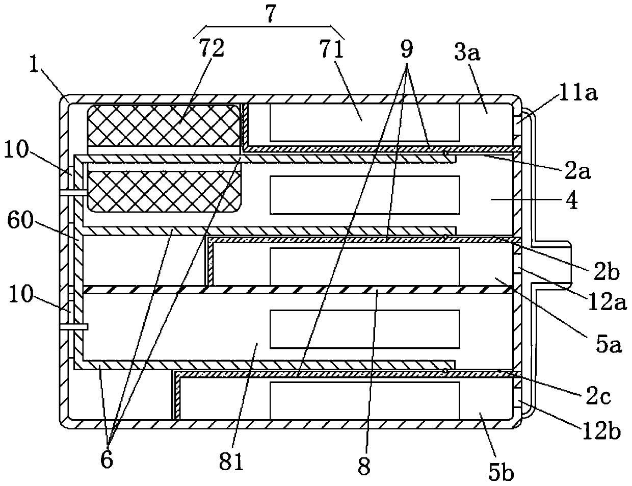
[0057] This embodiment provides a multi-cavity receiver. Compared with the structure of the receiver provided in Embodiment 1, the difference is that at least three sounding membranes 2 are provided, and at least three corresponding vibrating parts 6 are provided, such as figure 2 As shown, in the present embodiment, three sounding membranes 2 are provided, and the first sounding membrane 2a, the second sounding membrane 2b and the third sounding membrane 2c divide the hollow cavity into the first sound cavity 3a and the installation cavity arranged side by side in sequence. 4. The second sound cavity 5a, the isolation cavity 81 and the third sound cavity 5b, the first sound membrane 2a, the second sound membrane 2b and the third sound membrane 2c are respectively fixed on the support frame 9 located in the installation cavity 4 or the isolation cavity 81 on the wall and cover the inner cavity of the support frame 9, such as Figure 5 As shown, the support frame 9 has an L-sh...


PUM


Abstract

The invention provides a multi-sound-cavity telephone receiver. The multi-sound-cavity telephone receiver comprises a shell, a sound production membrane mechanism and at least one driving mechanism; at least two sound production membranes sequentially divide the hollow cavity into at least one main sound cavity, a mounting cavity and at least one secondary sound cavity which are not communicated with one another, the vibration parts are in one-to-one correspondence with the sound production membranes, and the driving mechanism drives all the the vibration parts to synchronously vibrate back and forth so as to drive the sound production membranes corresponding to the vibration parts to synchronously compress or expand the respective corresponding sound cavities. A magnetic isolation pad isarranged between the fixing section and the shell, so that the magnetic flux on any vibration part can be effectively ensured, and the magnetic flux leakage and the waste of the magnetic flux are reduced. When at least three sounding membranes are arranged, at least three vibration parts are correspondingly arranged, the vibration parts are connected together through a fixing section, the vibration part of any sound cavity is sleeved with a coil to drive all the vibration parts to vibrate synchronously, any sound production membrane corresponds to one sound cavity, and more sound production effects are generated through synchronous vibration sound production of the first sound cavity, the second sound cavity and the third sound cavity.

Description

technical field [0001] The invention belongs to the technical field of electroacoustic conversion, and in particular relates to a multi-cavity receiver. Background technique [0002] The receiver is an electroacoustic device that converts audio electrical signals into sound signals. It is widely used in communication terminal equipment such as mobile phones, fixed phones, and hearing aids to realize audio (voice, music) playback. The main principle of the receiver is to use electromagnetic induction and piezoelectric effect, and there are also capacitive earphones that use the principle of capacitors, and receivers that use the principle of electromagnetic induction mainly include moving iron receivers and moving coil receivers. [0003] For example, the Chinese patent document CN103747374A discloses a receiver with an improved housing, which includes a housing, a diaphragm, and an electromagnetic drive mechanism. The electromagnetic drive mechanism is fixed in the rear cav...

Claims


Application Information

Patent Timeline
Patent Type & Authority Applications(China)
IPC IPC(8): H04R9/08H04R9/02
CPCH04R9/08H04R9/02H04R2410/00
Inventor 陈晓明吴哲
Owner SUZHOU YICHUAN TECH CO LTD
Learn More