
Automatic screwing machine of floor slabs

An automatic locking screw machine, screw locking technology, applied in other manufacturing equipment/tools, drilling/drilling equipment, boring/drilling and other directions, can solve the problem of unfavorable workers' health, environmental noise workers, and finished floor strength. low level issues

Pending Publication Date: 2019-11-01
多维绿建科技(天津)有限公司 +2
View PDF1 Cites 7 Cited by
  • Summary
  • Abstract
  • Description
  • Claims
  • Application Information

AI Technical Summary

Problems solved by technology

[0002] The current floor fixing needs screws such as concrete or steel nails to fix; Environmental noise and high hazard to workers; this is not conducive to the health of workers, not to mention the improvement of production efficiency, so it is not suitable for a large number of or fast work
In the invention patent with the patent application number 201621158953.1, a drill row type floor automatic locking screw machine is proposed, which realizes the automatic operation of locking screws to a certain extent, but in actual use, there are still some deficiencies, for example: the equipment requires a lot of The use of compressed air is not conducive to on-site processing, the locking unit adopts pneumatic air batch, and the control is not accurate; it is not conducive to the processing of floors of different sizes; the strength of the processed finished floors is not high

Method used


Image

  • Automatic screwing machine of floor slabs
  • Automatic screwing machine of floor slabs
  • Automatic screwing machine of floor slabs

Examples


Embodiment Construction

[0023] The present invention will be described in detail below in conjunction with the accompanying drawings and embodiments.

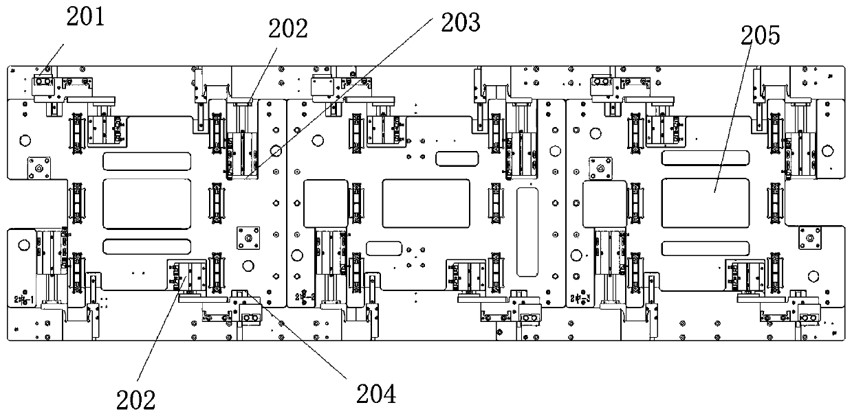
[0024] Such as Figure 1-7 As shown, a floor automatic screw locking machine, the screw locking machine includes a main frame 1, a horizontal workbench is arranged on the main frame 1, and a mold table 2 is arranged on the horizontal workbench; a transmission motor is also arranged on the horizontal workbench , the transmission motor slides along the horizontal workbench through the synchronous belt 5 traction mold table 2; two auxiliary brackets span the horizontal workbench, and an automatic punching unit 3 and an automatic locking unit 4 are respectively installed on the auxiliary brackets; the automatic punching Unit 3 includes a plurality of electric drilling machines, and the automatic locking unit 4 includes a plurality of automatic screw locking machines; the four corners of the mold table 2 and the middle parts of both sides are equipped with...


PUM


Abstract

The invention discloses an automatic screwing machine of floor slabs. The automatic screwing machine comprises a main machine frame, wherein a horizontal workbench is arranged on the main machine frame, and a die table is arranged on the horizontal workbench; a motor is further arranged on the horizontal workbench, and the motor drives the die table to slide along the horizontal workbench throughtraction by a synchronous belt; two auxiliary supports cross the horizontal workbench, and are correspondingly provided with automatic punching units and automatic locking units, the automatic punching units comprise a plurality of electric drilling machines, and the automatic locking units comprise a plurality of automatic screwing machines; and the four corners and the middle parts of the two side edges of the die table are provided with material pressing mechanisms, a plurality of metal strip locking mechanisms are arranged at the two side edges of the die table at equal intervals, and a material ejecting mechanism is arranged at the tail end of the horizontal workbench, and comprises a material ejecting air cylinder and a material ejecting supporting plate. According to the automatic screwing machine, the production process of automatic feeding, screwing and finished product discharging is finished by the machine, the condition of manual screwing is changed, the automatic control performance is high, the efficiency is high, and the operation is safe, easy and convenient.

Description

technical field [0001] The invention relates to the field of construction engineering, in particular to an automatic locking screw machine for floor slabs. Background technique [0002] The current floor fixing needs screws such as concrete or steel nails to fix; The environmental noise and the hazards to the workers are high; it is not conducive to the health of the workers, and it is not conducive to the improvement of production efficiency, so it is not suitable for a large amount of or fast work. In the invention patent with the patent application number 201621158953.1, a drill row type floor automatic locking screw machine is proposed, which realizes the automatic operation of locking screws to a certain extent, but in actual use, there are still some deficiencies, for example: the equipment requires a lot of The use of compressed air is not conducive to on-site processing, and the locking unit adopts pneumatic air batch, which is inaccurate in control; it is not condu...

Claims


Application Information

Patent Timeline
Patent Type & Authority Applications(China)
IPC IPC(8): B23P19/06B23B41/00B23P19/00B23P23/00
CPCB23P19/06B23P19/001B23P23/00B23B41/00
Inventor 孙刚陶红斌张赞李晓东
Owner 多维绿建科技(天津)有限公司
Learn More