Grounding ring, chamber, and physical vapor deposition apparatus

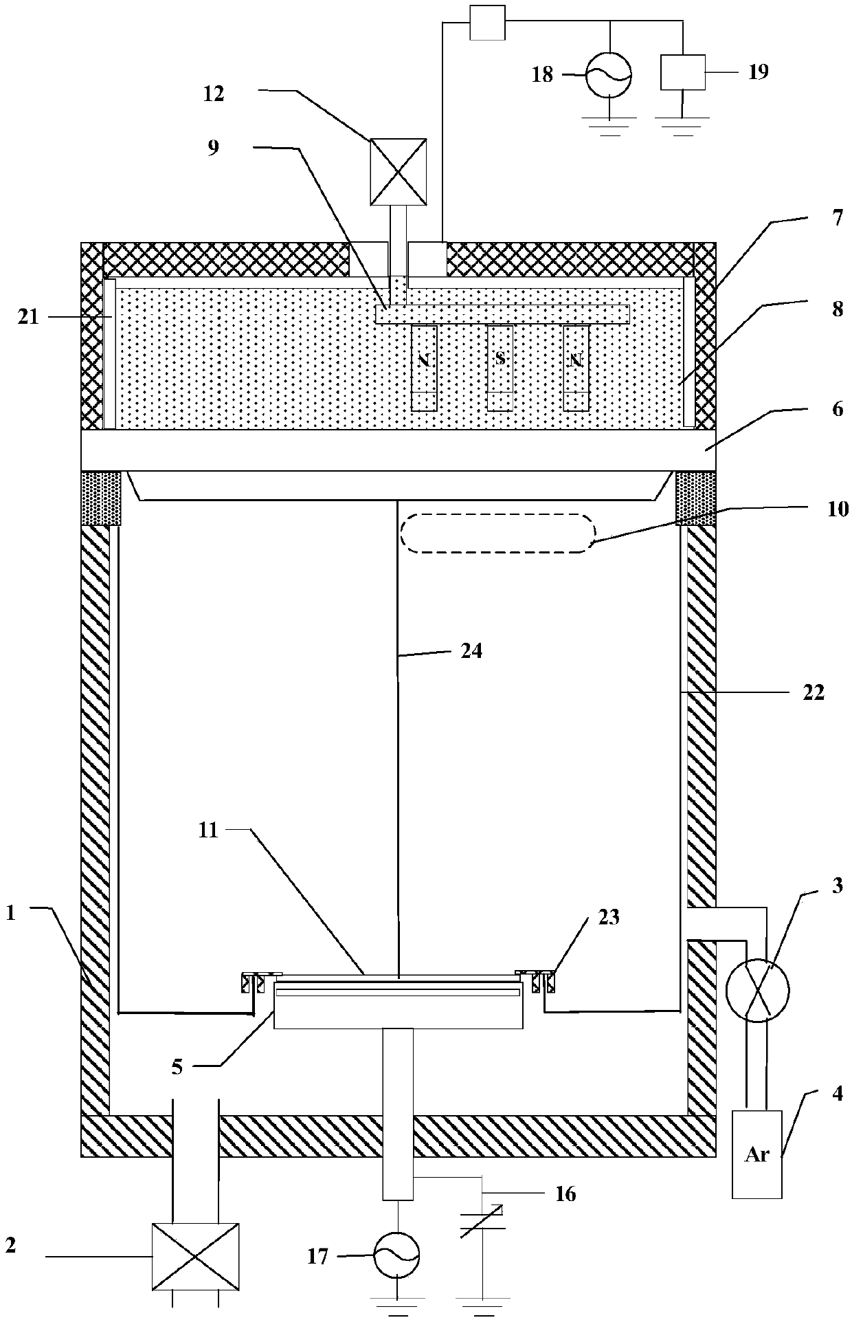
A grounding ring and chamber technology, used in ion implantation plating, metal material coating process, coating and other directions, can solve the problem that DC sputtering equipment is difficult to meet more advanced processes

Active Publication Date: 2019-11-01
BEIJING NAURA MICROELECTRONICS EQUIP CO LTD
View PDF7 Cites 3 Cited by
  • Summary
  • Abstract
  • Description
  • Claims
  • Application Information

AI Technical Summary

Problems solved by technology

[0003] Conventional DC sputtering equipment is difficult to meet the needs of more advanced proces

Method used


Image

  • Grounding ring, chamber, and physical vapor deposition apparatus
  • Grounding ring, chamber, and physical vapor deposition apparatus
  • Grounding ring, chamber, and physical vapor deposition apparatus

Examples


Embodiment Construction

[0032] In order to make the purpose, technical solutions and advantages of the embodiments of the present disclosure clearer, the technical solutions of the embodiments of the present disclosure will be clearly and completely described below in conjunction with the accompanying drawings of the embodiments of the present disclosure. Apparently, the described embodiments are some of the embodiments of the present disclosure, not all of them. Based on the described embodiments of the present disclosure, all other embodiments obtained by persons of ordinary skill in the art without creative effort fall within the protection scope of the present disclosure.

[0033] Unless otherwise defined, the technical terms or scientific terms used in the present disclosure shall have the usual meanings understood by those skilled in the art to which the present disclosure belongs. "First", "second" and similar words used in the present disclosure do not indicate any order, quantity or importan...


PUM


Abstract

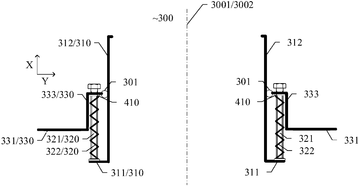
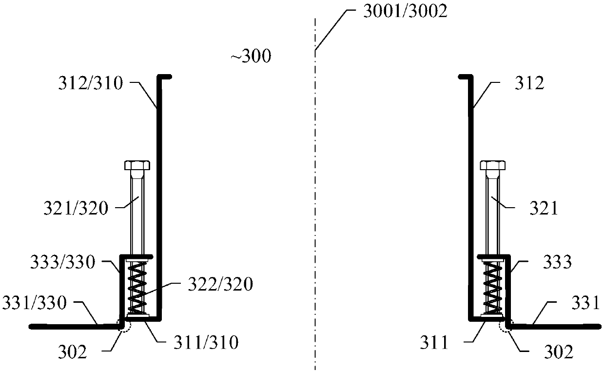
The present disclosure provides a grounding ring, a chamber, and a physical vapor deposition apparatus. The grounding ring includes a first conductive ring, a second conductive ring, and a plurality of elastic devices electrically connecting the first conductive ring and the second conductive ring, wherein a first central axis of the first conductive ring is parallel to or coincident with a secondcentral axis of the second conductive ring, and the plurality of elastic devices are configured such that the first conductive ring and the second conductive ring can move relative to each other in adirection of the first central axis. The elastic devices in the grounding ring may expand the adjustment range between the first conductive ring and the second conductive ring.

Description

technical field [0001] Embodiments of the present disclosure relate to a ground ring, a chamber, and a physical vapor deposition apparatus. Background technique [0002] In the integrated circuit manufacturing process, the Physical Vapor Deposition (Physical Vapor Deposition, PVD) method is widely used because of its better film consistency, uniformity and wider process window, and it can realize through-hole filling with high aspect ratio. Deposit many different layers of metal, hardmask, and other related material layers. However, if the physical vapor deposition sputtering equipment is to achieve the deposition of high-density TiN, other metal and metal compound high-density thin films, it needs to adjust the process parameters in many aspects, and if necessary, it is necessary to increase the hardware configuration to achieve the process goals to meet more advanced requirements. The needs of integrated circuit technology. [0003] Conventional DC sputtering equipment i...

Claims


Application Information

Patent Timeline
IPC IPC(8): C23C14/34C23C14/54
CPCC23C14/0036C23C14/34C23C14/54
Inventor 耿波罗建恒张超
Owner BEIJING NAURA MICROELECTRONICS EQUIP CO LTD
Why Eureka
Try Eureka