Roof outlet pipeline waterproof structure and construction method thereof

A technology for waterproof structures and pipes, applied to roofs, roof coverings, pipes, etc., can solve the problems of easy leakage of pipes and waterproof casings, achieve good waterproof effect, increase waterproof performance, and increase anti-crack performance.

Active Publication Date: 2019-11-01
北京世纪金鳄建筑装饰有限公司
View PDF7 Cites 5 Cited by
  • Summary
  • Abstract
  • Description
  • Claims
  • Application Information

AI Technical Summary

Problems solved by technology

[0005] The first object of the present invention is to provide a waterproof structure for the roof pipeline, which solves the problem of easy leakage between the pipeline and the waterproof casing, and has the advantage of good anti-seepage effect

Method used


Image

  • Roof outlet pipeline waterproof structure and construction method thereof

Examples


Embodiment 1

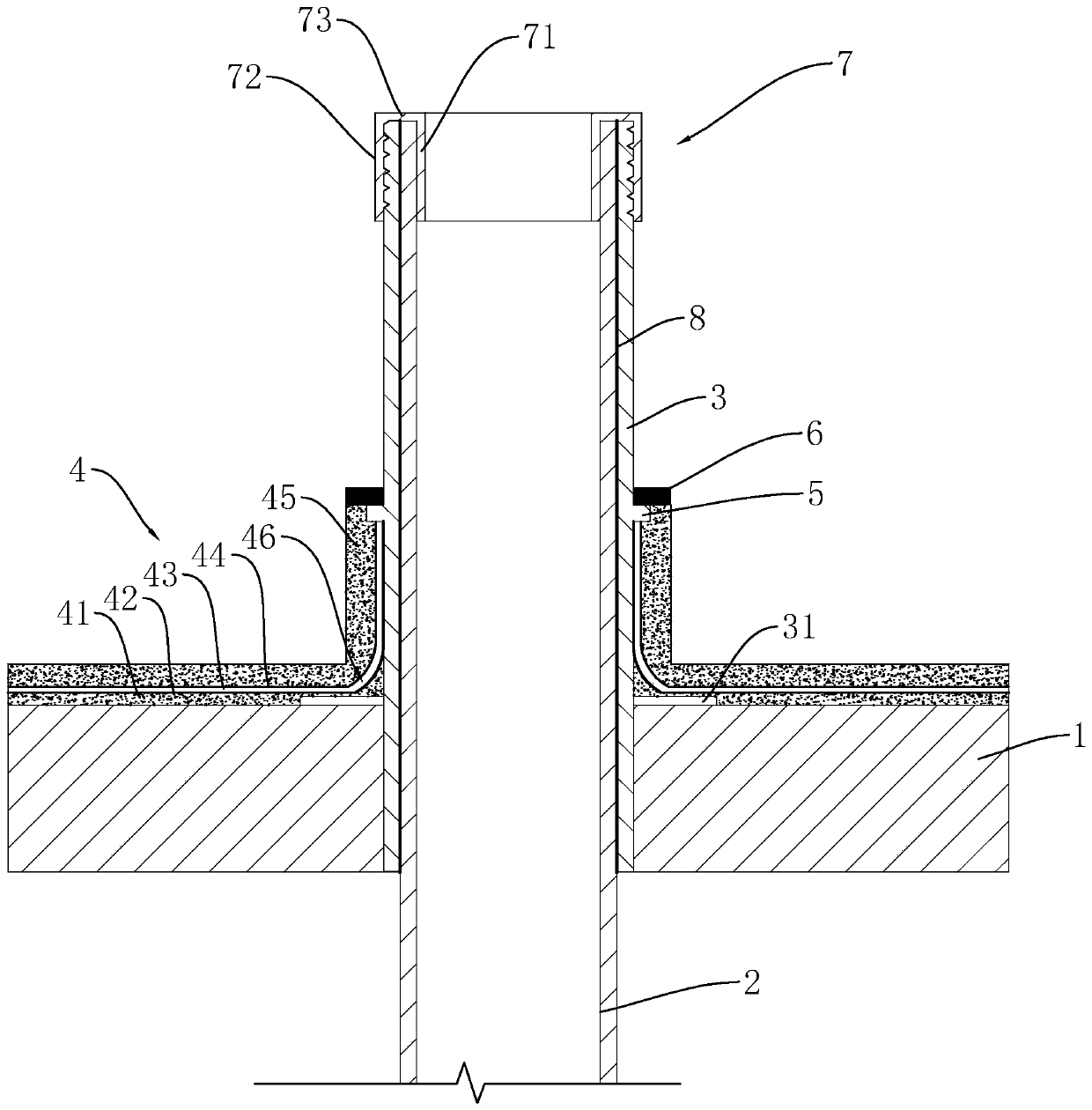
[0043] refer to figure 1, is a kind of waterproof structure of the roof pipeline disclosed by the present invention, including the pipeline 2 protruding from the roof. It is flush with the bottom surface of the roof, and the upper end is flush with the top surface of the pipe 2. A flange 31 is fixedly set on the outer wall of the waterproof casing 3, and the flange 31 is integrally formed with the waterproof casing 3. During installation, the flange 31 is attached to the roof. The waterproof casing 3 is provided with a waterproof layer 4, one end of the waterproof layer 4 extends to the roof, and the other end is folded upwards and wrapped on the waterproof casing 3. Among them, the roof is composed of cast-in-place roof board 1, and the waterproof coiled material 42 is SBS coiled material. The SBS coiled material has the advantages of no flow at high temperature, no brittle crack at low temperature, strong toughness, good elasticity, corrosion resistance, aging resistance, a...

Embodiment 2

[0051] refer to figure 1 , a construction method for a roof pipeline waterproof structure, comprising the following steps:

[0052] S1. Install the roof waterproof casing 3 on the roof cast-in-place slab 1 to ensure that the waterproof casing 3 is perpendicular to the roof and the bottom is flush with the bottom of the roof cast-in-place slab 1 .

[0053] S2. Apply waterproof ointment 8 on the outside of the pipeline 2, and install the pipeline 2 into the waterproof casing 3, so that the top surface of the pipeline 2 is flush with the top surface of the waterproof casing 3, so that the waterproof ointment 8 will connect the waterproof casing 3 and the waterproof casing 3. Gap filling between pipe 2.

[0054] S3. Buckle the connector 7 on the top of the pipe 2 and the waterproof sleeve 3, the inner wall of the waterproof sleeve 3 and the pipe 2 is located between the inner sleeve 71 and the outer sleeve 72, and use a wrench to screw the outer sleeve 72, make the connector 7 b...


PUM


Abstract

The invention relates to a roof outlet pipeline waterproof structure, and relates to the technical field of roof waterproofness. The structure comprises a pipeline protruding out of a roof, the pipeline is sleeved with a waterproof casing pipe, a flanging attached to the roof is fixedly arranged on the waterproof casing pipe, the waterproof casing pipe and the top of the pipeline are in seal connection through a connecting part, a waterproof layer is arranged outside the waterproof casing pipe, one end of the waterproof layer extends to the roof, the other end of the waterproof layer wraps thewaterproof casing pipe upwards, the waterproof layer sequentially comprises an inner bonding mortar layer, a waterproof coiled material, an outer bonding mortar layer, an alkali-resisting fiberglassgridding cloth and a concrete protection layer from inside to outside, the two ends of the concrete protection layer extend out of the waterproof coiled material and the alkali-resisting fiberglass gridding cloth, an annular protrusion with the top face flush with the top face of the concrete protection layer and inserted into the concrete protection layer is fixedly arranged on the outer side ofthe waterproof casing pipe, and a sealant is arranged on the annular protrusion and the top face of the concrete protection layer. The structure has the advantages of being convenient to mount and good in anti-seepage effect.

Description

technical field [0001] The invention relates to the technical field of roof waterproofing, in particular to a waterproof structure of a roof outlet pipeline and a construction method thereof. Background technique [0002] At present, in most buildings, pipes often need to extend out of the roof, and the place where the pipes pass through the roof is relatively weak, which may easily lead to problems such as water seepage. Therefore, it is necessary to improve the waterproof performance of the connection between the roof and the pipes. [0003] The existing application number for reference is CN201220401472.4, the date of authorization announcement is February 13, 2013, and the name of the utility model is: the waterproof node of the roof pipe. This application relates to a waterproof node of the roof pipeline, which includes a pipeline protruding from the roof. The pipe sleeve is provided with a pipe sleeve, and a waterproof layer is provided on the periphery of the pipe sle...

Claims


Application Information

Patent Timeline
Patent Type & Authority Applications(China)
IPC IPC(8): E04D13/00F16L5/02
CPCE04D13/00F16L5/02
Inventor 左建霞
Owner 北京世纪金鳄建筑装饰有限公司
Why Eureka
Try Eureka