Refrigeration system

A refrigeration system and condenser technology, applied in refrigerators, air conditioning systems, refrigeration components, etc., can solve the problems of unsuccessful refrigeration system design, unavoidable toxic and harmful substances, damage to the ozone layer, etc. The effect of low overall power consumption

Inactive Publication Date: 2019-11-01
高雪峰
View PDF0 Cites 1 Cited by
  • Summary
  • Abstract
  • Description
  • Claims
  • Application Information

AI Technical Summary

Problems solved by technology

At present, most refrigeration systems use tetrafluoroethane instead of freon as the working medium. Although this medium overcomes the shortcomings of freon in destroying the ozone layer, it has the following problems as a refrigerant: 1. Tetrafluoroethane is extremely strong The effect of the greenhouse gas on the Earth’s atmosphere is 3300 times that of the greenhouse gas carbon dioxide within 20 years of its entry into the atmosphere. Although there will be attenuation later, it will still be 1300 times that of carbon dioxide in the following 100 years times, within 500 years, it is 400 times; 2. Although tetrafluoroethane is used as a refrigerant, although it has no obvious toxicity, users will frequently experience the phenomenon of "air conditioner not cooling" during use, and in this case, the vast majority Part of it is the so-called "fluorine deficiency", that is, the leakage of refrigerant, in fact, it has gone into the atmosphere; 3. The manufacture of tetrafluoroethane is a very large industrial group. There will be a large amount of toxic and harmful substances that will inevitably pollute the environment and even cause harm
Using a clean refrigerant that does not produce a greenhouse gas effect as the working medium can solve the above problems, but the current refrigeration system has no successful design in this regard

Method used


Image

  • Refrigeration system
  • Refrigeration system
  • Refrigeration system

Examples


Embodiment Construction

[0015] The present invention will be further described below through specific embodiments and accompanying drawings.

[0016] see figure 1

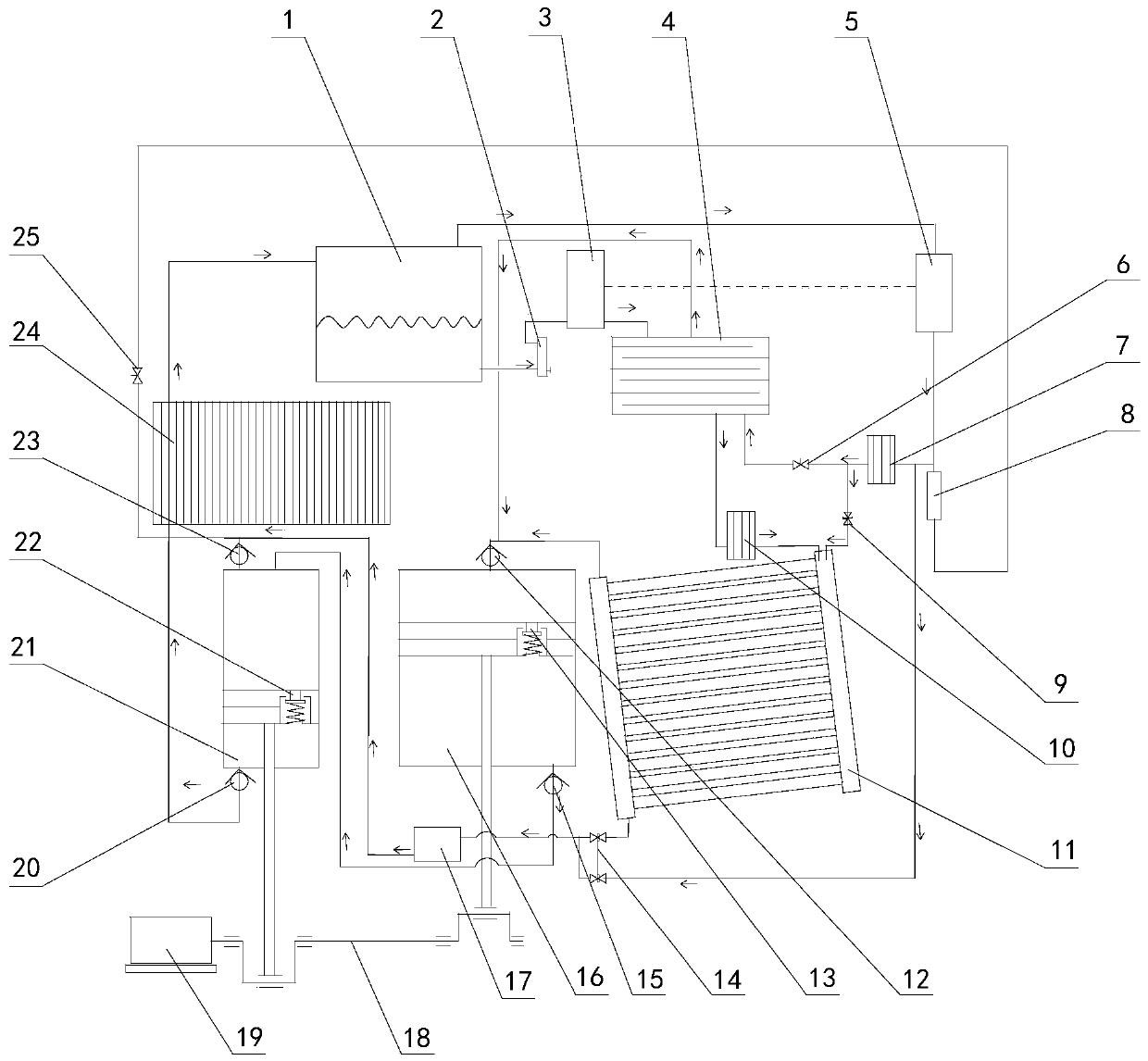
[0017] The refrigerating system provided by the present invention has a condenser 24 and an evaporator 11, the outlet of the condenser 24 is connected to the inlet of a liquid-gas separator 1, and the exhaust port of the liquid-gas separator 1 is connected to the first liquid-gas separator 1 through a condensation drier 5. The inlet of the secondary surface cooler 7 is connected, the outlet of the first secondary surface cooler 7 is connected with the air inlet of the primary evaporator 4 and the gas working medium pipeline of the evaporator 11, the gas outlet of the primary evaporator 4 and the The vacuum interface of the evaporator 11 is connected to the inlet port of a vacuum cylinder 16 through the first one-way valve 12, and the liquid outlet port of the liquid-gas separator 1 is connected to the liquid inlet port of the primary eva...


PUM


Abstract

A refrigeration system is provided with a condenser, an evaporator and a power device; the evaporator is provided with an evaporation pipeline, a liquid working medium pipeline and a gas working medium pipeline, and the evaporation pipeline is filled with metal heat conduction wires; and the condenser is connected with a liquid-gas separator, the liquid-gas separator is connected with a first auxiliary surface cooler and a first-stage evaporator, the first auxiliary surface cooler is connected with the first-stage evaporator and the evaporator, the first-stage evaporator is connected with a vacuum cylinder, the first-stage evaporator is connected with a liquid working medium pipeline, the vacuum cylinder is connected with a booster cylinder, the evaporator is connected with the booster cylinder, the booster cylinder is connected with the condenser, and piston rods of the vacuum cylinder and the booster cylinder are connected with a power device. A working medium is separated into liquid and gas by the liquid-gas separator and then enters the first-stage evaporator, the liquid and the dried gas enter the evaporator to be evaporated, the purpose of refrigeration is achieved, and thegas and the liquid discharged by the first-stage evaporator and the evaporator are discharged into the condenser by the booster cylinder and then enter the liquid-gas separator to complete one cycle.

Description

technical field [0001] The invention relates to refrigeration technology, in particular to a refrigeration system. Background technique [0002] The existing air-conditioning refrigeration system using Freon or tetrafluoroethane as the working medium is mainly composed of an evaporator, a compressor, a condenser, and an expansion valve connected in sequence. This refrigeration system has high refrigeration efficiency and good effect, and is currently widely used refrigeration system. At present, most refrigeration systems use tetrafluoroethane instead of freon as the working medium. Although this medium overcomes the shortcomings of freon in destroying the ozone layer, it has the following problems as a refrigerant: 1. Tetrafluoroethane is extremely strong The effect of the greenhouse gas on the Earth’s atmosphere is 3300 times that of the greenhouse gas carbon dioxide within 20 years of its entry into the atmosphere. Although there will be attenuation later, it will still ...

Claims


Application Information

Patent Timeline
IPC IPC(8): F24F5/00F25B43/00F25B41/00F25B41/40
CPCF24F5/0003F25B43/006F25B41/00
Inventor 高雪峰
Owner 高雪峰
Why Eureka
Try Eureka