
Light barrier device of photoetching machine

A technology of light baffles and lithography machines, which is applied in the direction of microlithography exposure equipment, photolithography exposure devices, photomechanical equipment, etc., can solve the problems of complex structure and high space occupancy of light baffle devices, and achieve the goal of solving light baffle devices. The structure is relatively complex, the structure is simple, and the effect of normal work is improved

Inactive Publication Date: 2019-11-01
SHANGHAI NANPRE MECHANICS
View PDF4 Cites 0 Cited by
  • Summary
  • Abstract
  • Description
  • Claims
  • Application Information

AI Technical Summary

Problems solved by technology

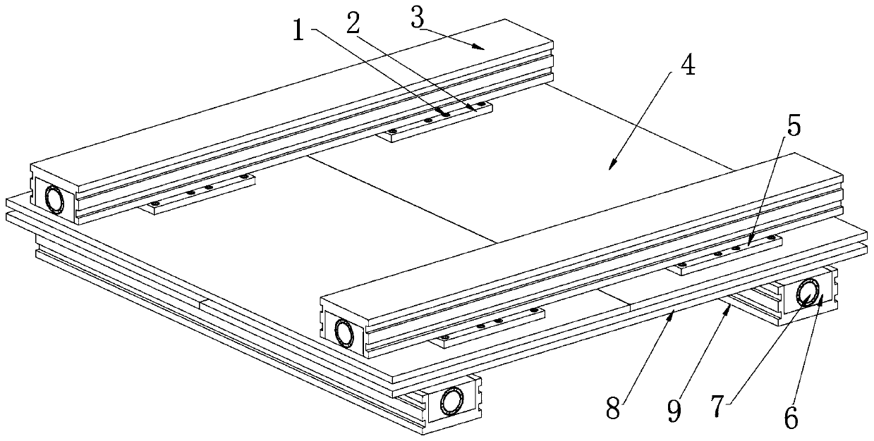
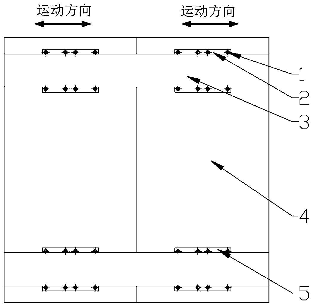
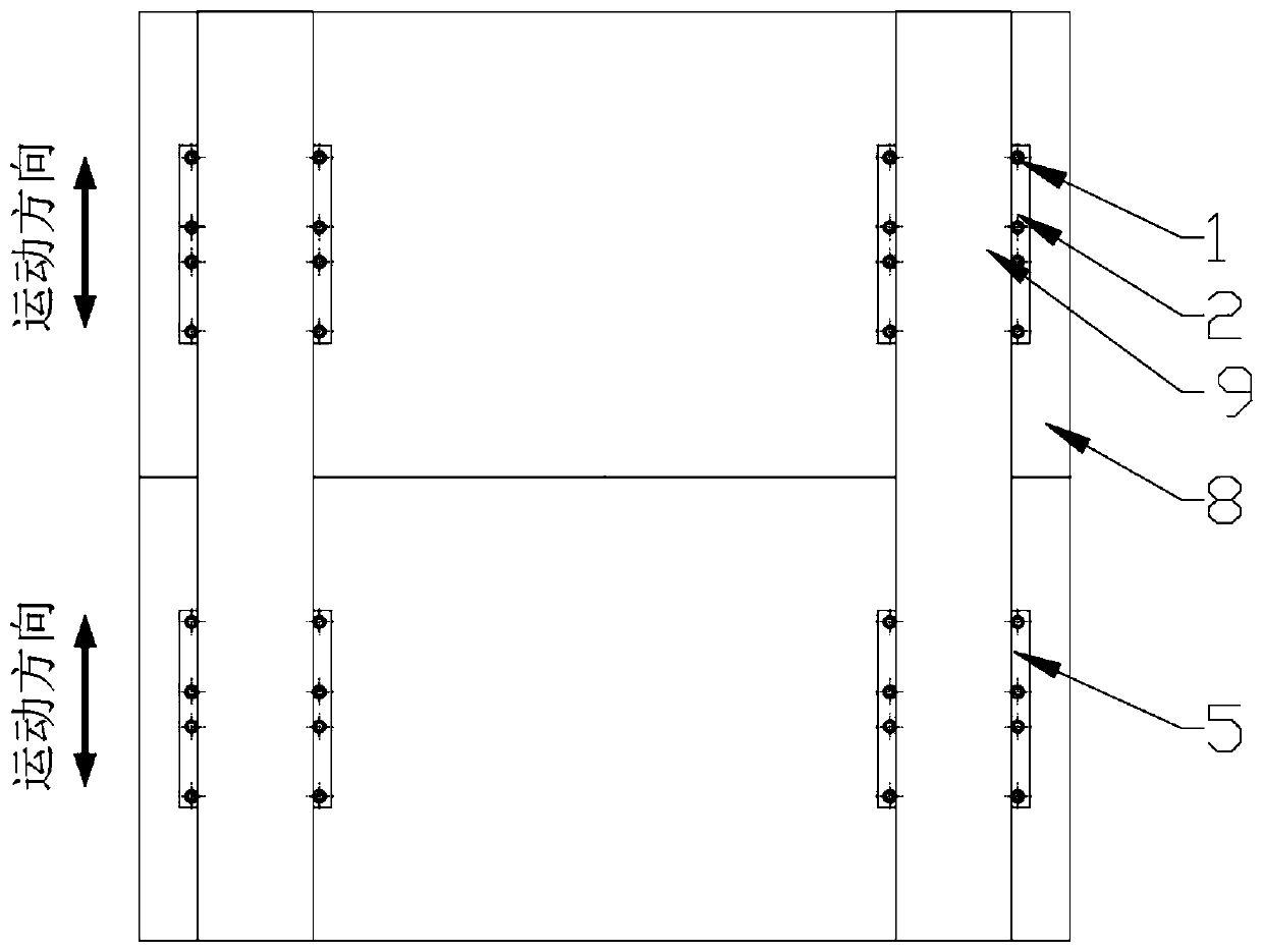
[0004] The object of the present invention is to provide a baffle device for a lithography machine, so as to solve the problems that the structure of the light baffle device for a lithography machine is relatively complicated and the space occupancy rate is high in the above-mentioned background technology

Method used


Image

  • Light barrier device of photoetching machine
  • Light barrier device of photoetching machine
  • Light barrier device of photoetching machine

Examples


Embodiment Construction

[0021] In order to make the technical problems, technical solutions and beneficial effects to be solved by the present invention clearer, the present invention will be further described in detail below in conjunction with the accompanying drawings and embodiments. It should be understood that the specific embodiments described here are only used to explain the present invention, not to limit the present invention.

[0022] In describing the present invention, it should be understood that the terms "upper", "lower", "front", "rear", "left", "right", "top", "bottom", "inner", " The orientation or positional relationship indicated by "outside", etc. is based on the orientation or positional relationship shown in the drawings, and is only for the convenience of describing the present invention and simplifying the description, rather than indicating or implying that the referred device or element must have a specific orientation, so as to Specific orientation configurations and ope...


PUM


Abstract

The invention relates to the technical field of integrated circuit production equipment and particularly discloses a light barrier device of a photoetching machine. The light barrier device comprisestwo front light barriers. The front side and the rear side of the upper end of the front light barriers are connected with a corresponding upper guide rail through a first sliding block and a second sliding block respectively. A ball screw is arranged in the upper guide rail. Two rear light barriers are correspondingly arranged below the front light barriers. The left side and the right side of the lower end of each rear light barrier are connected with a corresponding lower guide rail through a first sliding block and a second sliding block respectively. A ball screw is arranged in the lowerguide rail. The front light barriers are driven to move left and right in the horizontal direction through the ball screw in the upper guide rail. Meanwhile, the ball screws in the lower guide rails are used for driving the rear light barriers to move forwards and backwards in the horizontal direction. After that, the rear light barriers and the front light barriers are used in cooperation to forma light transmitting opening. The device is simple in structure. The problems that an existing light barrier device of the photoetching machine is complex in structure and high in space occupancy rate are solved.

Description

technical field [0001] The invention relates to the technical field of integrated circuit production equipment, in particular to a light blocking device of a photolithography machine. Background technique [0002] Mask Aligner is also called mask alignment exposure machine, exposure system, lithography system, etc., as a kind of equipment often used in semiconductor integrated circuit manufacturing (that is, the core equipment for producing large-scale integrated circuits), it generally It is to use ultraviolet rays to remove the protective film on the surface of the wafer through the template, so as to facilitate the subsequent production of integrated circuits by washing the impurities remaining on the surface of the wafer with pure water (the simple steps of producing integrated circuits generally include the following three steps: using the template to remove the wafer The protective film on the round surface; the wafer is soaked in a corrosive agent, and the part that l...

Claims


Application Information

Patent Timeline
IPC IPC(8): G03F7/20
CPCG03F7/7015G03F7/70833
Inventor 郎小虎
Owner SHANGHAI NANPRE MECHANICS
Learn More