
Submerged membrane assembly

A technology of immersed membrane and membrane unit, which is applied to chemical instruments and methods, special treatment targets, sustainable biological treatment, etc. The effect of reducing land and investment costs, eliminating gas accumulation in pipelines, and simplifying operation management

Pending Publication Date: 2019-11-05
SHANGHAI SUPRATEC MEMBRANE TECH CO LTD +1
View PDF0 Cites 0 Cited by
  • Summary
  • Abstract
  • Description
  • Claims
  • Application Information

AI Technical Summary

Problems solved by technology

[0005] 1) Dry centrifugal pumps are used for relatively large-scale water volumes. The suction pipeline needs to be equipped with vacuum devices (vacuum pumps and vacuum tanks), which are expensive and complex in operation and management. Centrifugal pumps are prone to cavitation, which affects the life of the pump. and system reliability;
[0006] 2) For the small amount of water to be treated, a dry self-priming pump is used, which is expensive and prone to gas accumulation at local high points of the suction pipeline;
[0007] 3) The dry pump needs to be equipped with a pump room, which occupies a large area and has high civil construction costs
[0009] 1) Affect the flow of water in the pipeline, and even no water in severe cases;
[0010] 2) Air accumulation in the pipeline will cause cavitation of the pump, affect the stable operation of the pump and reduce the life of the pump

Method used


Image

  • Submerged membrane assembly

Examples


Embodiment 1

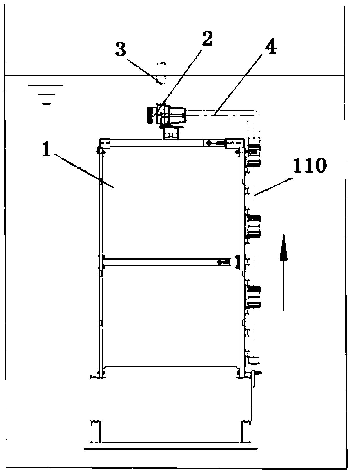
[0027] Such as figure 1 As shown, a submerged membrane unit includes a membrane unit 1, a submersible pump 2 and a second outlet pipe 3. Both the membrane unit 1 and the submersible pump 2 are arranged below the water surface, and the liquid outlet of the membrane unit 1 is connected to the The liquid inlet of the submersible pump 2 is connected. Normally, the larger the water output, the greater the power of the submersible pump 2 is required. One end of the second water outlet pipe 3 is connected to the liquid outlet of the submersible pump 2. The second The other end of the outlet pipe 3 protrudes above the water surface line, and is connected to an external water storage facility or directly discharged.

Embodiment 2

[0029] Such as figure 1 As shown, a submerged membrane unit includes a membrane unit 1, a submersible pump 2 and a second outlet pipe 3. Both the membrane unit 1 and the submersible pump 2 are arranged below the water surface, and the liquid outlet of the membrane unit 1 is connected to the The liquid inlet of the submersible pump 2 is connected. Normally, the larger the water output, the greater the power of the submersible pump 2 is required. One end of the second water outlet pipe 3 is connected to the liquid outlet of the submersible pump 2. The second The other end of the outlet pipe 3 protrudes above the water surface line, and is connected to an external water storage facility or directly discharged.

[0030] Wherein, there is a first water outlet pipe 110 on the membrane module 1, the first water outlet pipe 110 is upward along the side wall of the membrane module 1, and the liquid inlet of the first water outlet pipe 110 is connected with the liquid outlet of the memb...

Embodiment 3

[0032] Such as figure 1 As shown, a submerged membrane unit includes a membrane unit 1, a submersible pump 2 and a second outlet pipe 3. Both the membrane unit 1 and the submersible pump 2 are arranged below the water surface, and the liquid outlet of the membrane unit 1 is connected to the The liquid inlet of the submersible pump 2 is connected. Normally, the larger the water output, the greater the power of the submersible pump 2 is required. One end of the second water outlet pipe 3 is connected to the liquid outlet of the submersible pump 2. The second The other end of the outlet pipe 3 protrudes above the water surface line, and is connected to an external water storage facility or directly discharged.

[0033] Wherein, there is a first water outlet pipe 110 on the membrane module 1, the first water outlet pipe 110 is upward along the side wall of the membrane module 1, and the liquid inlet of the first water outlet pipe 110 is connected with the liquid outlet of the memb...


PUM


Abstract

The invention relates to a submerged membrane assembly, which comprises a membrane assembly, a submersible pump and a second water outlet pipe, wherein the membrane assembly and the submersible pump are arranged below a water surface, the liquid outlet of the membrane assembly is communicated to the liquid inlet of the submersible pump, one end of the second water outlet pipe is connected to the liquid outlet of the submersible pump, and the other end of the second water outlet pipe extends above the water surface line. According to the present invention, by replacing the dry pump with the submersible pump, the gas accumulation in the pipeline is eliminated, and the manufacturing cost is greatly reduced; the pump is installed under the water, such that the water outlet pipe is changed fromthe negative pressure state of the dry pump to the positive pressure state so as not to affect the normal operation of the submersible pump, not to accumulate gas in the pipeline, and to ensure the water outlet continuity and the reliability of the entire submerged membrane assembly; and the arrangement of the vacuumizing device and the pump room is not required, such that the operation management is simplified, the land occupation and the investment cost are reduced, and the application in MBR can be promoted.

Description

technical field [0001] The invention relates to the field of sewage treatment, in particular to a submerged membrane module. Background technique [0002] Membrane Bio-Reactor (MBR) is a new water treatment technology based on membrane separation materials. This technology has the characteristics of good and stable effluent quality, high treatment load, small equipment footprint, and simple operation and management. With the continuous advent of various new membranes, membrane technology has gradually expanded to urban drinking water purification, reclaimed water reuse, urban sewage treatment, medicine, food, biological engineering and other fields. [0003] Today, when global water resources are in short supply and pollution is becoming more and more serious, the use of membrane technology at home and abroad is becoming more and more common. According to the different forms of membrane systems, it can be divided into two types: pressure membrane modules and submerged membra...

Claims


Application Information

Patent Timeline
IPC IPC(8): C02F3/12
CPCC02F3/1273C02F2203/006C02F2303/14Y02W10/10
Inventor 白英张显超白海龙茹岩坤陈瑞瑞牛四芳
Owner SHANGHAI SUPRATEC MEMBRANE TECH CO LTD
Learn More