
Draining ditch forming device

A technology for forming devices and drainage ditches, which is applied in water supply devices, water conservancy projects, artificial waterways, etc., to achieve the effect of less manual participation, good pouring effect and high efficiency

Pending Publication Date: 2019-11-05
ZHONGJIAN SUIDAO CONSTR CO LTD
View PDF0 Cites 5 Cited by
  • Summary
  • Abstract
  • Description
  • Claims
  • Application Information

AI Technical Summary

Problems solved by technology

[0004] Aiming at the problems existing in the above-mentioned prior art, the present invention provides a drainage ditch forming device to solve the problems existing in the drainage ditch pouring construction in the prior art

Method used


Image

  • Draining ditch forming device
  • Draining ditch forming device
  • Draining ditch forming device

Examples


Embodiment Construction

[0026] The following will clearly and completely describe the technical solutions in the embodiments of the present invention with reference to the accompanying drawings in the embodiments of the present invention. Obviously, the described embodiments are only some, not all, embodiments of the present invention. Based on the embodiments of the present invention, all other embodiments obtained by persons of ordinary skill in the art without making creative efforts belong to the protection scope of the present invention.

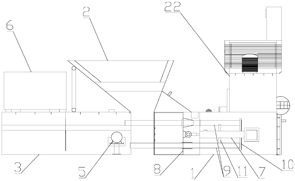
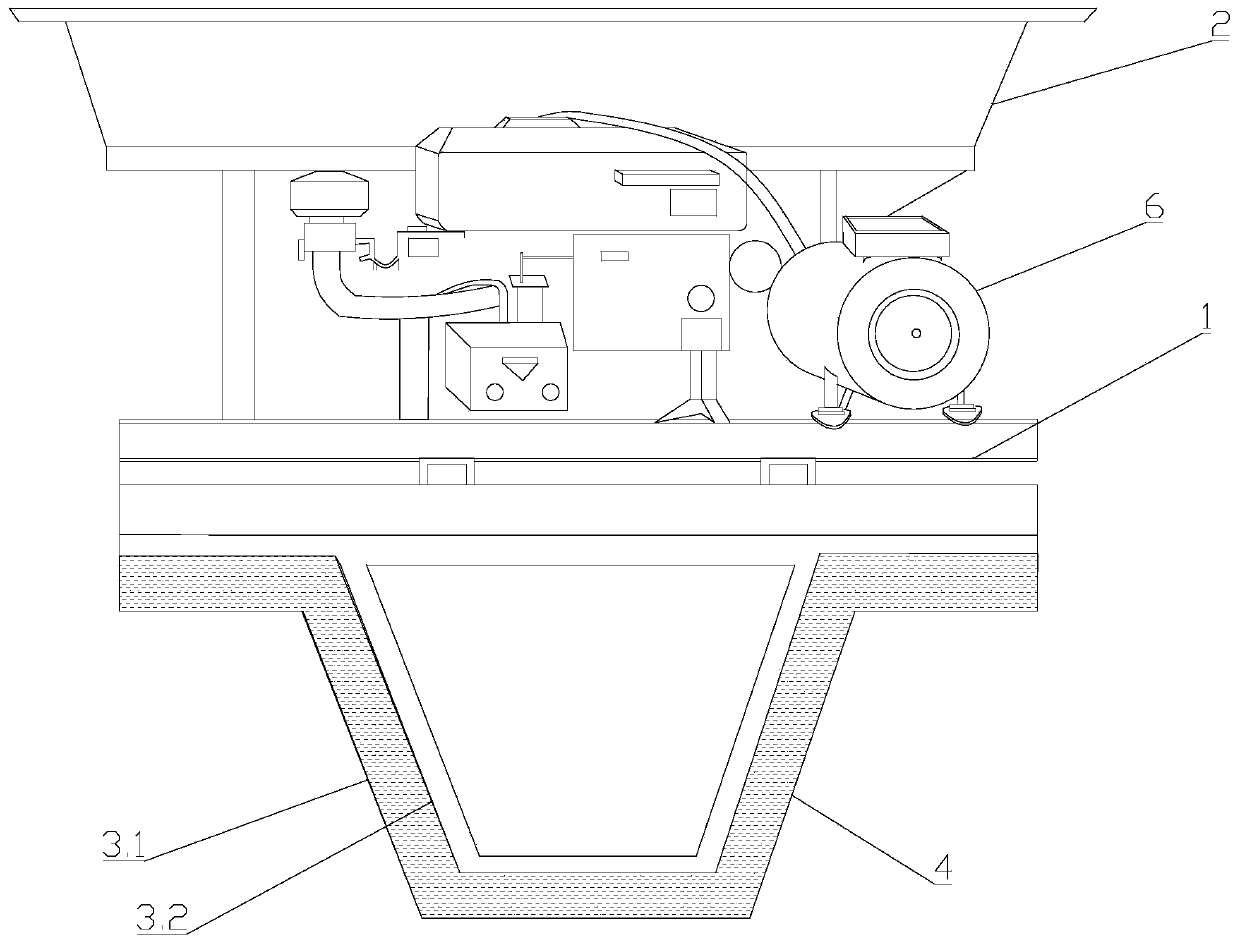
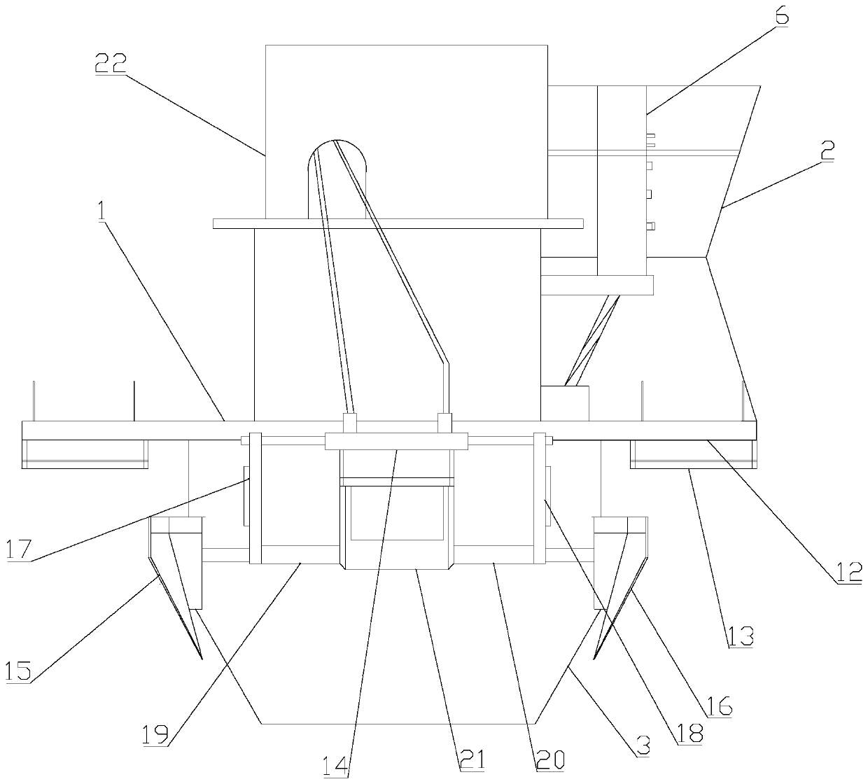
[0027] figure 1 It is a structural schematic diagram of a drainage ditch forming device according to an embodiment of the present invention, figure 2 for figure 1 front view diagram of image 3 for figure 1 The rear view diagram, combined with Figure 1-Figure 3 , The forming device of the embodiment of the present invention includes a frame 1, a feed hopper 2, a forming mold 3 and a propulsion assembly.

[0028] combine Figure 1-Figure 3 , the feed ho...


PUM


Abstract

The invention belongs to the technical field of civil construction and particularly relates to a draining ditch forming device. A feeding hopper of the device is fixedly arranged on a rack. A feedingopening is formed in the top of the feeding hopper. A discharging opening is formed in the bottom of the feeding hopper. A forming die is fixedly arranged at one end in the length direction of the rack. The forming die and the cross section of a draining ditch are consistent. A propelling assembly is arranged at the other end in the length direction of the rack. A discharging opening of the feeding hopper is formed between the upper end of the forming die and the propelling assembly. The output portion of the propelling assembly can contract toward the direction of the forming die. The draining ditch forming device has the characteristics that manual participation is little, the efficiency is high, time and labor are saved, and the concrete pouring effect is good, thus the forming qualityof the draining ditch is ensured, and the draining ditch forming device has very good practicality.

Description

technical field [0001] The invention belongs to the technical field of civil construction, and in particular relates to a drainage ditch forming device. Background technique [0002] The drainage ditch refers to the ditch that guides the water collected in the side ditch, intercepting ditch, and near the roadbed, in the crop field, and in the low-lying places near the residence to the roadbed, crop field, and residential area. [0003] At present, the cross-sectional form of the drainage ditch is generally trapezoidal. The trapezoidal groove has the advantages of stable structure and no need for frequent maintenance after completion. For the pouring construction of trapezoidal drainage ditch, the commonly used method is to manually form the formwork according to the design thickness of the bottom and body of the drainage ditch. The formwork is mostly a few simple wooden boards. , Finishing are all carried out manually, there is low efficiency, slow progress, long constructi...

Claims


Application Information

Patent Timeline
Patent Type & Authority Applications(China)
IPC IPC(8): E02B5/02E03F3/06E03F3/04
CPCE02B5/02E03F3/06E03F3/046
Inventor 邓余华曾送勃祁彬黄克峰张礼焰潘才权余昆王田张琪
Owner ZHONGJIAN SUIDAO CONSTR CO LTD
Learn More