
Imaging logging short section structure based on rotary guiding and rotary guiding well drilling device

A rotary steering, imaging logging technology, applied in directional drilling, drilling equipment, wellbore/well components, etc., can solve the problems of single function, weakened formation evaluation function, lag in formation measurement parameters, etc., to achieve accurate measurement accuracy and shortened time. The effect of accurate assembly length and measurement data

Active Publication Date: 2019-11-05
BC P INC CHINA NAT PETROLEUM CORP +1
View PDF8 Cites 1 Cited by
  • Summary
  • Abstract
  • Description
  • Claims
  • Application Information

AI Technical Summary

Problems solved by technology

[0004] Therefore, the main problems of existing LWD tools are: 1) Conventional LWD gamma tools are mainly used for edge detection and lithology identification, lacking azimuth and peripheral imaging functions; The instrument is mainly used for formation evaluation. Usually, the measurement of high-resistivity formations is inaccurate, which weakens the formation evaluation function and affects the quality of steerable drilling. It is difficult to meet the production requirements of logging engineering integration, real-time decision-making integration, and precise steerable drilling; The LWD tool has a single function, and usually requires several tools to be used together, resulting in too long a tool, lagging formation measurement parameters, and making it difficult to guide drilling in a timely manner

Method used


Image

  • Imaging logging short section structure based on rotary guiding and rotary guiding well drilling device
  • Imaging logging short section structure based on rotary guiding and rotary guiding well drilling device
  • Imaging logging short section structure based on rotary guiding and rotary guiding well drilling device

Examples


Embodiment Construction

[0034] The present invention will be further described in detail below in conjunction with specific embodiments, which are explanations of the present invention rather than limitations.

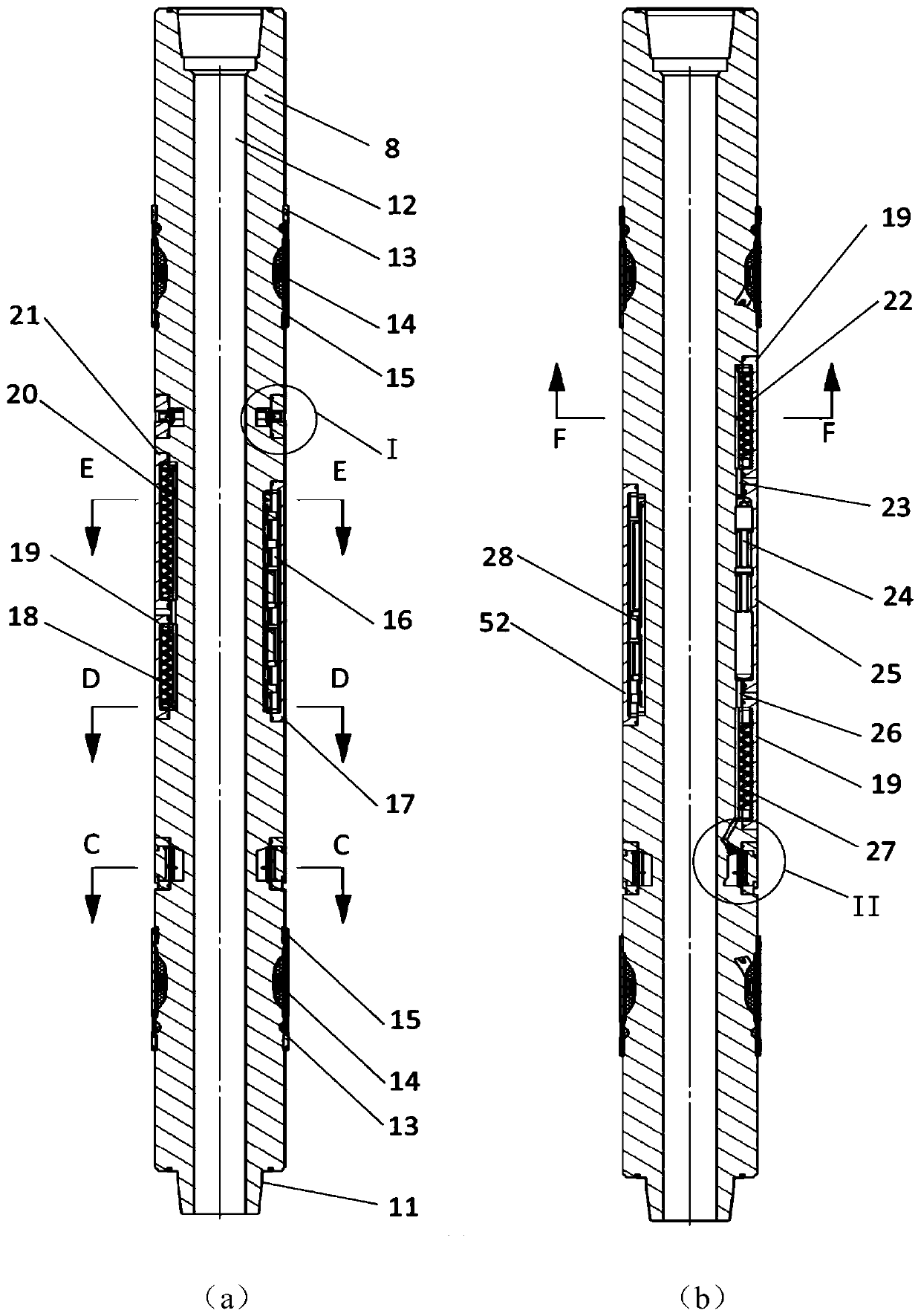
[0035] refer to figure 1 , the present invention is based on the rotary steerable imaging logging nipple structure, including a drill collar body 8, on which a resistivity transmitting antenna assembly 9, a button electrode assembly 7, and a resistivity receiving electrode are sequentially arranged on the drill collar body 8 from top to bottom. The plate assembly 4 and the resistivity receiving antenna assembly 3 are also provided with a gamma imaging detector assembly 5 and a downhole control circuit assembly 6 on the drill collar body 8 .

[0036] The resistivity transmitting antenna assembly 9 is used to transmit the constant current required to detect downhole signals, and the current is transmitted to the formation through the drill collar body 8 . The button electrode assembly 7 is use...


PUM


Abstract

The invention provides an imaging logging short section structure based on rotary guiding. The imaging logging short section structure based on rotary guiding comprises a button electrode assembly, aspecific resistance receiving polar plate assembly, a specific resistance receiving antenna assembly and an integrated gamma imaging detector assembly, wherein the button electrode assembly, the specific resistance receiving polar plate assembly and the specific resistance receiving antenna assembly are arranged below a specific resistance transmitting antenna assembly from top to bottom; the button electrode assembly is closest to a transmitting antenna; and as a button electrode has a small receiving surface and a relatively high resolution ratio, a well wall specific resistance signal can be obtained. The specific resistance receiving polar plate assembly is capable of measuring the specific resistance value of a slightly remote stratum and judging the signal of distance from an instrument to the boundary of the reservoir in advance. The specific resistance receiving antenna assembly is farthest from the transmitting antenna, and the specific resistance receiving distance is farther, so that the specific resistance signal of a position near a drill bit can be obtained, thereby facilitating the forward-looking stratum evaluation and guiding function. The imaging logging short section structure based on rotary guiding has relatively short drill collar design length, relatively complete measurement parameters and a measured value closer to the drill bit.

Description

technical field [0001] The invention belongs to the field of geological drilling, and relates to logging-while-drilling equipment in oil drilling, in particular to a rotary-steering-based imaging logging nipple structure and a rotary-steering drilling device. Background technique [0002] At present, the development of heterogeneous and unconventional oil and gas fields poses greater challenges to steerable drilling engineering. It is difficult to meet the drilling requirements of complex oil and gas wells only by downhole logging while drilling and engineering parameter measurement. [0003] At present, the rotary steerable head and the gamma-ray and resistivity imaging instruments put into commercial application at home and abroad are basically independent drill collar sub-section instruments. If they are to be used in combination, the independent sub-sections must be connected and combined in field application Together, the upper and lower parts are respectively connected...

Claims


Application Information

Patent Timeline
IPC IPC(8): E21B49/00E21B47/12E21B17/16E21B7/04
CPCE21B49/00E21B47/12E21B17/16E21B7/04Y02A90/30
Inventor 陈鹏郭怡潇朱军刘枭杨善森卫一多吴显代志平陈辉刘刚鲁晔
Owner BC P INC CHINA NAT PETROLEUM CORP
Learn More