
A scanner for three-dimensional imaging with an anti-shake device

A 3D imaging and scanner technology, applied in the scanner field, achieves the effects of simple and novel structure, easy operation, and improved anti-shake efficiency

Active Publication Date: 2021-10-01
李文正
View PDF12 Cites 0 Cited by
  • Summary
  • Abstract
  • Description
  • Claims
  • Application Information

AI Technical Summary

Problems solved by technology

[0003] The purpose of the present invention is to provide a scanner for three-dimensional imaging with an anti-shake device in order to solve the above problems, which solves the current existing problems

Method used


Image

  • A scanner for three-dimensional imaging with an anti-shake device
  • A scanner for three-dimensional imaging with an anti-shake device
  • A scanner for three-dimensional imaging with an anti-shake device

Examples


Embodiment Construction

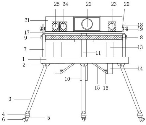
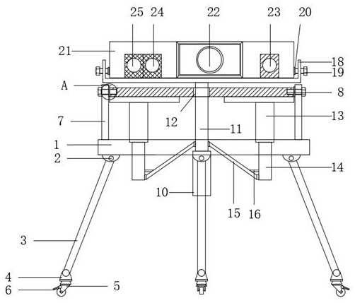
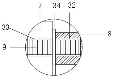
[0020] like Figure 1-4 As shown, this specific embodiment adopts the following technical solutions: a scanner for three-dimensional imaging with an anti-shake device, including a hollow load-bearing plate 1 and a shock-absorbing device 4, the lower end of the hollow load-bearing plate 1 is evenly connected with several hinges 2 The end of the hinge 2 away from the hollow bearing plate 1 is connected with a triangular load-bearing bracket 3, and the end of the triangular load-bearing bracket 3 away from the hinge 2 is connected with a shock absorber 4, and the shock absorber 4 consists of a spring groove 26, Spring bottom plate 27, linear chute 28, buffer spring 29, linear slide block 30 and universal wheel connection block 31 are formed, and described damping device 4 is provided with spring groove 26 near the side of triangular bearing support 3, and described spring groove 26 is fixedly connected with the triangular load-bearing bracket 3, the bottom of the spring groove 26...


PUM


Abstract

The invention discloses a scanner for three-dimensional imaging with an anti-shake device, which comprises a hollow load-bearing plate and a shock absorbing device. A plurality of hinges are evenly connected to the lower end of the hollow load-bearing plate, and a triangular load-bearing bracket is connected to the end of the hinge away from the hollow load-bearing plate. , the end of the triangular load-bearing bracket away from the hinge is connected with a shock absorbing device. In the present invention, a No. 1 piston rod is connected under the body of the three-dimensional imaging scanner, and both sides of the No. 1 piston rod are fixedly connected to the No. 2 piston rod through fixed oblique rods. In this way, the 3D imaging scanner body can ensure that the No. 1 piston rod does not shake during the rising process, achieving the anti-shake effect. The vibration of the three-dimensional imaging scanner body caused by the device passing through bumpy roads is reduced. The invention has a simple and novel structure, is easy to operate, and greatly improves the anti-shake efficiency of the three-dimensional imaging scanner body.

Description

Technical field: [0001] The invention belongs to the field of scanners, in particular to a scanner for three-dimensional imaging with an anti-shake device. Background technique: [0002] The optical scanning device is a device that uses collimated light beams for non-contact target object scanning and distance measurement. By rotating the collimated light beam (such as laser) used for distance measurement within a certain range, it is possible to scan and measure objects in a certain environment and extract the contour information of the environment. Compared with methods such as ultrasonic waves and image detection, the use of optical scanning ranging devices can achieve very high scanning and ranging accuracy, and the ranging speed is fast. Therefore, it has a very high application value in the industrial and civil fields. It is widely used in the fields of robot autonomous mapping and navigation positioning (SLAM), 3D scene reconstruction, security detection, etc., but t...

Claims


Application Information

Patent Timeline
Patent Type & Authority Patents(China)
IPC IPC(8): F16M11/04F16M11/18F16F15/04G01S17/08
CPCF16F15/04F16M11/046F16M11/18G01S17/08
Inventor 李文正
Owner 李文正
Learn More