Movable junction box of circuit cable
A technology of circuit cables and junction boxes, applied in the direction of electrical components, clamping/spring connections, etc., can solve the problems of poor connection stability and safety, achieve the effects of lead wire and control safety, avoid falling off, and improve safety
- Summary
- Abstract
- Description
- Claims
- Application Information
AI Technical Summary
Problems solved by technology
Method used
Image

Examples
Embodiment 1
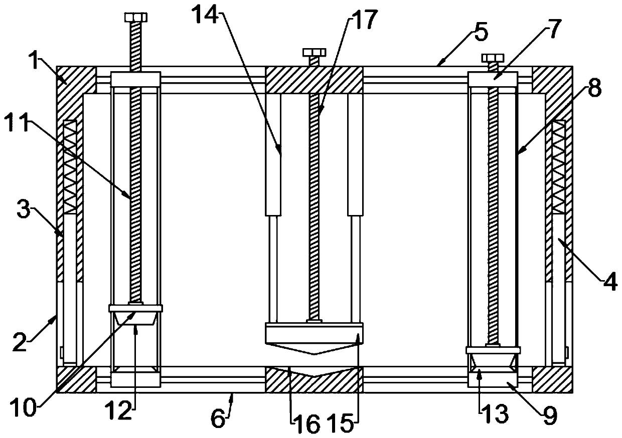
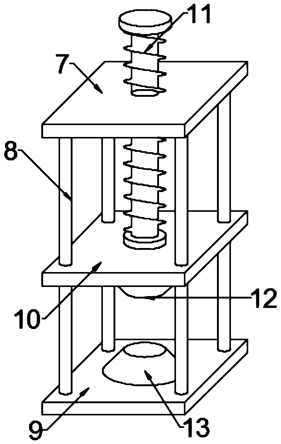
[0021] see Figure 1~2 , in an embodiment of the present invention, a movable junction box for a circuit cable includes a casing 1, and both ends of the casing 1 are provided with an incoming line structure for the cable to enter, and the casing 1 is also provided with a Fix the cable and connect the conductive wiring structure. The upper side wall of the housing 1 is symmetrically provided with the upper sliding groove 5 centered on the wiring structure. The lower side wall of the housing 1 is symmetrically provided with the wiring structure as the center. The lower sliding groove 6, the upper sliding groove 5 and the lower sliding groove 6 are correspondingly arranged, and the upper sliding groove 5 and the lower sliding groove 6 on the same side are respectively slidably installed and provided with a lead wire clamping structure for fixing the traction cable. The lead clamping structure comprises an upper slide plate 7 slidably fitted in the upper slide groove 5, a lower sl...
Embodiment 2
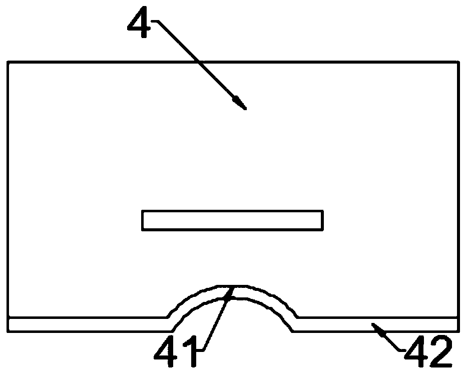
[0025] see image 3 , in an embodiment of the present invention, a movable junction box for a circuit cable, on the basis of Embodiment 1, the end cover 4 is a thin plate of insulating material, preferably insulating ceramic or hard polymer material, and the end cover 4 Surface sticking, welding or integrated molding is provided with a handle protrusion, and the middle part of the lower surface of the end cover 4 is embedded with a sub-arc-shaped clamping port 41, and the lower surface of the end cover 4 and the clamping port 41 are attached A fixed rubber pad 42 is provided, and the fixed rubber pad 42 is a soft pad made of silica gel. In this way, the handle protrusion on the surface of the end cover 4 can be used to press the end cover 4 into the assembly groove 3. After the cable is inserted, the end cover 4 can be loosened to compress the cable elastically by the spring, and the cable is placed In the clamping port 41, and with the fixing rubber pad 42, the cable can be ...
PUM
 Abstract
Description
Claims
Application Information
 - Generate Ideas
- Intellectual Property
- Life Sciences
- Materials
- Tech Scout
- Unparalleled Data Quality
- Higher Quality Content
- 60% Fewer Hallucinations
Browse by: Latest US Patents, China's latest patents, Technical Efficacy Thesaurus, Application Domain, Technology Topic, Popular Technical Reports.
© 2025 PatSnap. All rights reserved.Legal|Privacy policy|Modern Slavery Act Transparency Statement|Sitemap|About US| Contact US: help@patsnap.com