Novel high-frequency high-voltage silicon stack circuit
A high-frequency, high-voltage, silicon stack technology, applied in the field of new high-frequency, high-voltage silicon stack circuits, can solve the problems of rectifier diode voltage equalization failure, insulation failure, equipment failure, etc., to prevent high-voltage silicon stack from collapsing Impact ability, the effect of preventing unbalanced pressure equalization
- Summary
- Abstract
- Description
- Claims
- Application Information
AI Technical Summary
Problems solved by technology
Method used
Image
Examples
Embodiment 1
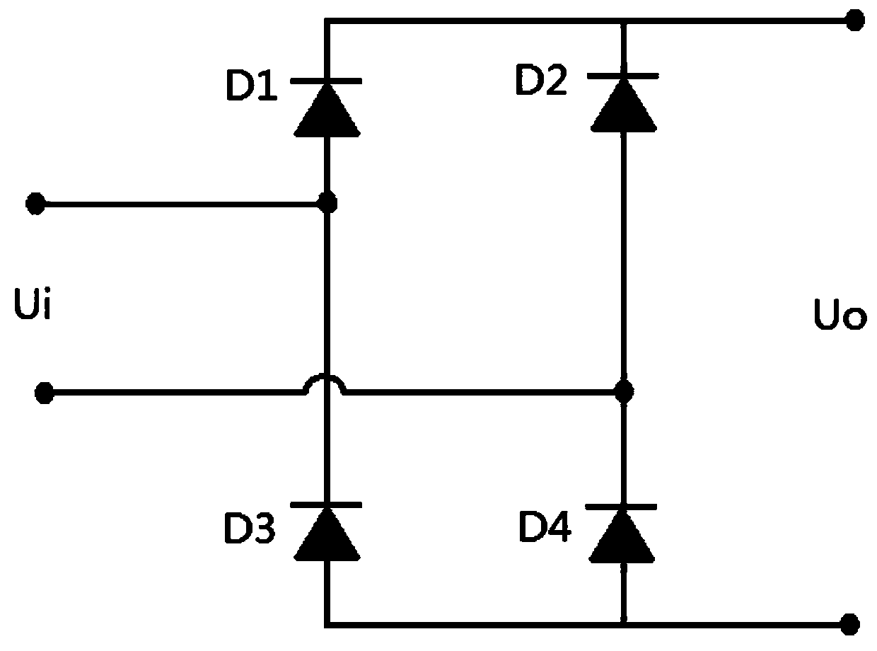
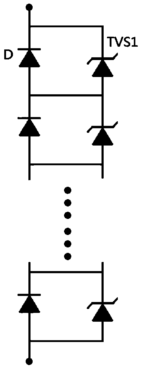
[0022] Such as figure 1 The equivalent circuit schematic of a high voltage silicon stack is shown. A new high-frequency and high-voltage silicon stack circuit includes rectifying diode modules D1 / D2 / D3 / D4 composed of a plurality of rectifying diodes D connected in series. Each rectifying diode module is equivalent to a large high-voltage-resistant rectifying diode. The four rectifier diode modules D1 / D2 / D3 / D4 form a full-bridge rectifier circuit, the input terminal Ui of the full-bridge rectifier circuit is connected to an external AC power supply, and the output terminal Uo of the full-bridge rectifier circuit outputs direct current. Such as figure 2 As shown, a positively connected unidirectional transient suppressor diode TVS1 is arranged in parallel at both ends of each rectifier diode D, and the clamping voltage of the transient suppressor diode TVS1 is smaller than the maximum reverse voltage of the rectifier diode D.
[0023] The unidirectional transient suppression ...
Embodiment 2
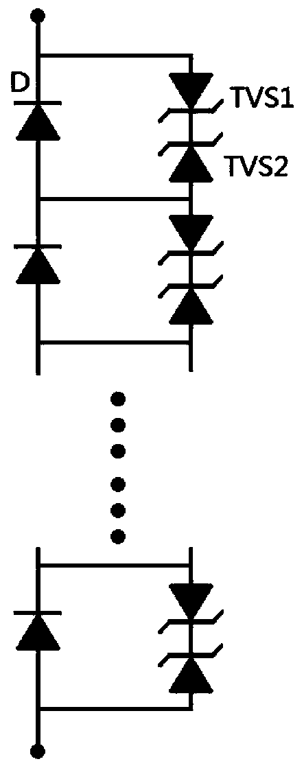
[0025] Such as figure 1 The equivalent circuit schematic of a high voltage silicon stack is shown. A new type of high-frequency high-voltage silicon stack circuit, including four rectifier diode modules D1 / D2 / D3 / D4 composed of multiple rectifier diodes D in series, each rectifier diode module is equivalent to a large high-voltage resistant rectifier diode. The four rectifier diode modules D1 / D2 / D3 / D4 form a full-bridge rectifier circuit, the input terminal Ui of the full-bridge rectifier circuit is connected to an external AC power supply, and the output terminal Uo of the full-bridge rectifier circuit outputs direct current. Two bidirectional transient suppression diodes are arranged in parallel at both ends of each rectifier diode D, and the bidirectional transient suppression diodes can be provided with two unidirectional transient suppression diodes with opposite polarities and connected in series to achieve the same effect.
[0026] Such as image 3 As shown, the unidi...
Embodiment 3
[0029] Such as figure 1 The equivalent circuit schematic of a high voltage silicon stack is shown. A new type of high-frequency high-voltage silicon stack circuit, including four rectifier diode modules D1 / D2 / D3 / D4 composed of multiple rectifier diodes D in series, each rectifier diode module is equivalent to a large high-voltage resistant rectifier diode. The four rectifier diode modules D1 / D2 / D3 / D4 form a full-bridge rectifier circuit, the input terminal Ui of the full-bridge rectifier circuit is connected to an external AC power supply, and the output terminal Uo of the full-bridge rectifier circuit outputs direct current. Such as Figure 4As shown, a bidirectional transient suppression diode TVS3 is arranged in parallel at both ends of each rectifier diode D. A bidirectional TVS diode is used. When the rectifier diode works normally, the TVS diode does not conduct. When the current direction changes, the TVS diode absorbs a large amount of instantaneous energy and clamp...
PUM
 Abstract
Description
Claims
Application Information
 - R&D
- Intellectual Property
- Life Sciences
- Materials
- Tech Scout
- Unparalleled Data Quality
- Higher Quality Content
- 60% Fewer Hallucinations
Browse by: Latest US Patents, China's latest patents, Technical Efficacy Thesaurus, Application Domain, Technology Topic, Popular Technical Reports.
© 2025 PatSnap. All rights reserved.Legal|Privacy policy|Modern Slavery Act Transparency Statement|Sitemap|About US| Contact US: help@patsnap.com


