Punching device of numerical control enclosed machine
A technology of punching device and enclosing machine, which is applied in the directions of feeding device, positioning device, storage device, etc., can solve the problems of low work efficiency of workers, slow manual punching speed, and increased cost.
- Summary
- Abstract
- Description
- Claims
- Application Information
AI Technical Summary
Problems solved by technology
Method used
Image

Examples
Embodiment
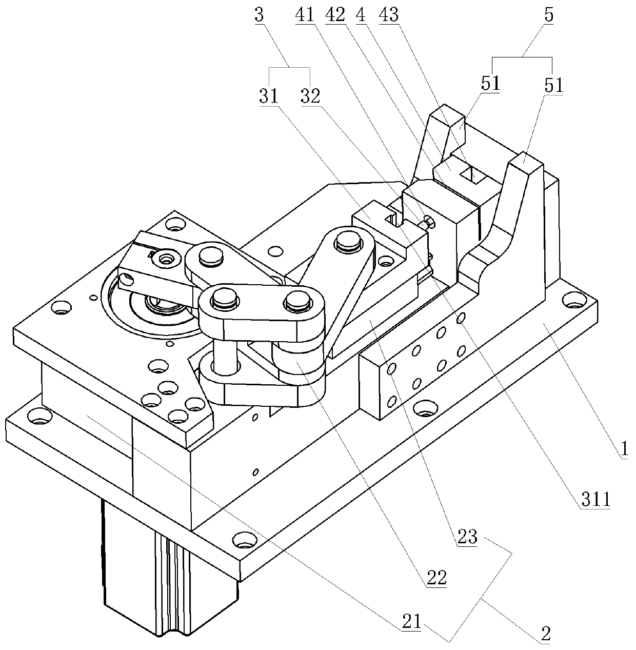
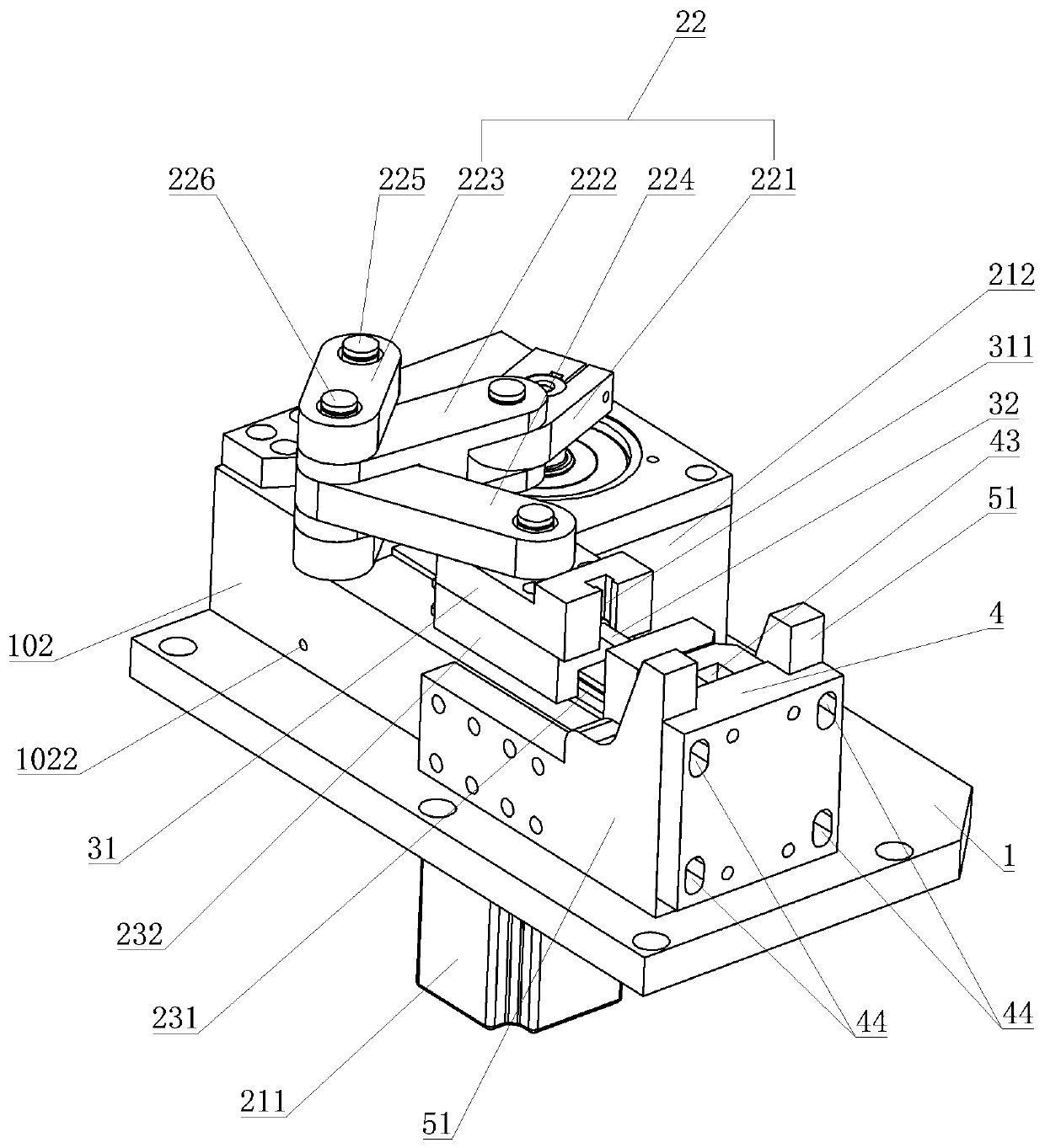
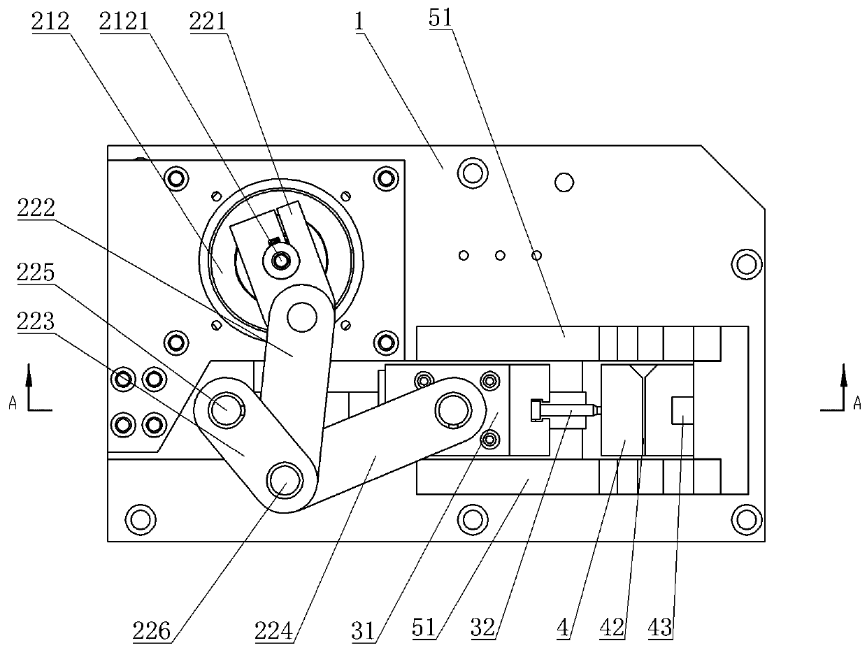
[0029] Example: as attached Figures 1 to 5 As shown, a punching device of a numerical control enclosing machine includes a mounting frame 1, a punching driving device, a punching part 3 and a punching backing plate 4 are arranged on the mounting frame 1, and the punching part 3 includes a punching Head 32 and punch mounting seat 31, described punch 32 is installed on the punch mounting seat 31, described punching backing plate 4 is provided with punch through hole 41 and material strip through groove 42, described punch through The hole 41 vertically passes through the strip channel 42, the end of the punch 32 away from the punch mounting seat 31 extends into the punch through hole 41, and the punching driving device drives the punching part 3 toward the punching backing plate 4 Linear reciprocating motion.
[0030] as attached Figures 6 to 8 As shown, the punch 32 includes a punch tail end 321, a punch rod 322 and a punch tip 323 which are integrally arranged, the diamete...
PUM
 Abstract
Description
Claims
Application Information
PatSnap Eureka turns technology decisions into work you can execute. Powered by our Innovation Knowledge Graph, it runs expert workflows across engineering, life sciences, materials and intellectual property. Get your review-ready output in minutes.


