Bottle cap positioning method for laser code printing of bottle caps

A positioning method and bottle cap technology, applied in laser welding equipment, copy/marking method, temperature recording method, etc., can solve problems such as easy deviation, bottle cap screening, poor coding quality, etc., to achieve convenient coding, Improve work efficiency and ensure the effect of accuracy

Inactive Publication Date: 2019-11-08
CHANGXING QIKAI MECHANICAL EQUIP CO LTD
View PDF9 Cites 2 Cited by
  • Summary
  • Abstract
  • Description
  • Claims
  • Application Information

AI Technical Summary

Problems solved by technology

[0005] The purpose of the present invention is to address the deficiencies of the existing technology, by combining the three tasks of feeding, positioning and coding, and discharging, and utilizing the linkage between components, the bottle caps after screening are accurately The positioning is on the coding station, thus solving the problem that the existing bottle cap conveying device does not have the function of positioning the bottle cap, making it prone to deviation when it is located at the printing dock, making the coding quality not good enough, and in the Before coding, the bottle caps cannot be screened, and it is a technical problem that requires human screening

Method used


Image

  • Bottle cap positioning method for laser code printing of bottle caps
  • Bottle cap positioning method for laser code printing of bottle caps
  • Bottle cap positioning method for laser code printing of bottle caps

Examples


Embodiment 1

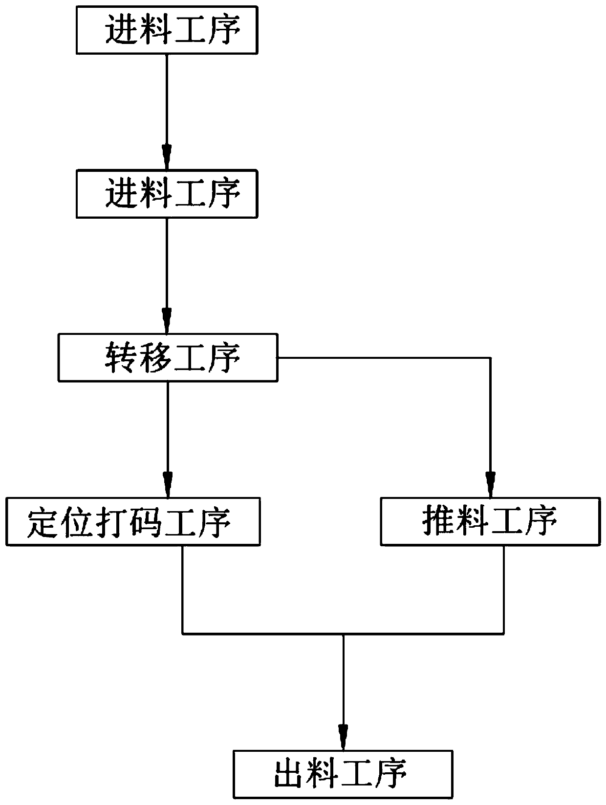
[0044] Such as figure 1 , figure 2 As shown, a bottle cap positioning method for laser marking, including:

[0045] Step 1, the feeding process, the bottle caps 100 from the belt feeding device 12 enter the feeding pipe 11 in sequence;

[0046] Step 2, the screening process, the material receiving column 34 of the feeding assembly 3 is located on the feeding station, the bottle cap with the cap facing down falls on the material receiving column 34 arranged under the guide tube 11, and the rest remain in the guide tube 11. Inside the material pipe 11;

[0047] Step 3, the transfer process, when the bottle cap falls on the material guide tube 11, the material receiving column 34 rotates in a circle, the material receiving column 34 rotates from the loading station to the coding station, and the bottle cap in the material guide tube 11 falls on the In the first receiving basin 13;

[0048] Step 4, positioning coding process, the rotating wheel 38 rotates to the bottom along ...

Embodiment 2

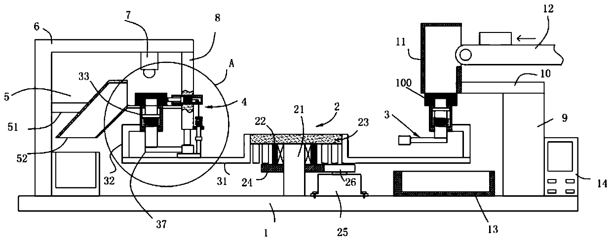
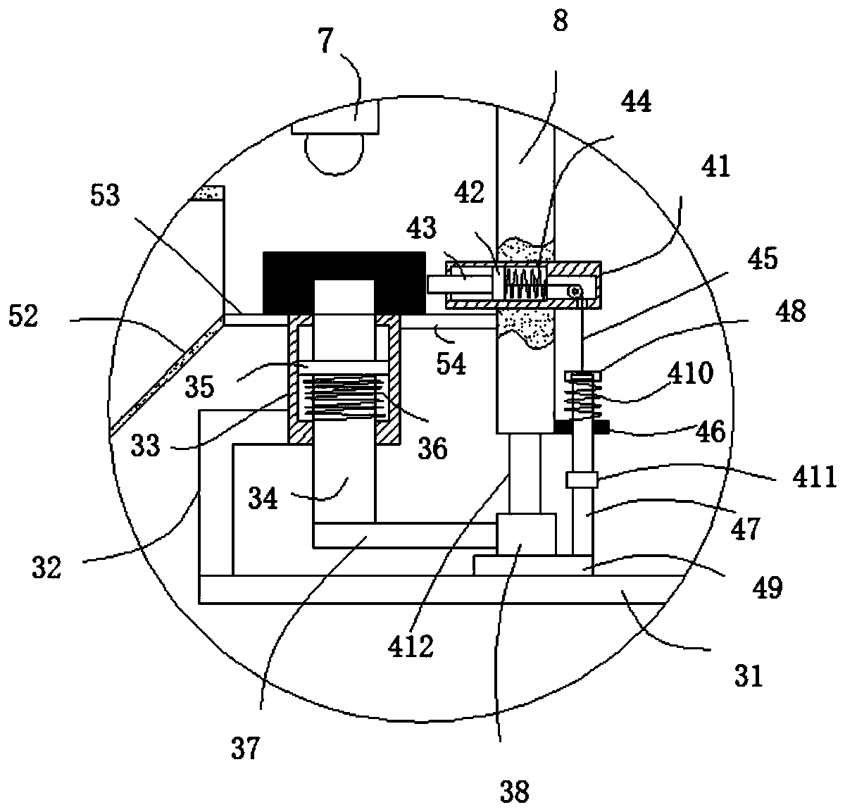
[0062] Such as figure 2 As shown, the components that are the same as or corresponding to those in the first embodiment are marked with the corresponding reference numerals in the first embodiment. For the sake of simplicity, only the differences from the first embodiment will be described below. The difference between this embodiment two and embodiment one is:

[0063] A bottle cap positioning device for packaging bottle cap coding, comprising a base 1 and a controller 14 fixed on the base 1, an L-shaped fixing plate 6 is fixed on the base 1, and a vertical The laser marking terminal 7 and the mounting plate 8 are equipped with a stripping assembly 4 on the mounting plate 8, a receiving assembly 5 matching the stripping assembly 4 is installed on the L-shaped fixed plate 6, and a driving assembly 2 is installed on the base 1. The driving assembly 2 is fixed with feeding assemblies 3 arranged in a circular array, the leftmost feeding assembly 3 is located below the laser mar...


PUM


Abstract

The invention relates to a bottle cap positioning method for laser code printing of bottle caps. The method comprises the steps that 1, the feeding process is carried out; 2, the screening process iscarried out; 3, the transferring process is carried out; 4, the positioning and code printing process is carried out; 5, the material returning process is carried out; and 6, the discharging process is carried out, specifically, when a rotating wheel continues to move and is separated from the plane of a contact plate, a second spring and a third spring are restored to the original positions, a material returning rod bounces out to hit against the bottle caps located on a right material receiving table and a left material receiving table, the bottle caps enter a material receiving cylinder under the action of inertia and drops down into a second collecting basin so as to complete collection. The method has the advantage that the technical problems that an existing conveying device for bottle caps does not have the bottle cap positioning function, so that deviation can be easily caused when the bottle caps are located at the position of a code printing head, the code printing quality isnot good enough, in addition, the bottle caps cannot be screened before code printing and need to be screened manually can be solved.

Description

technical field [0001] The invention relates to the technical field of bottle cap processing, in particular to a bottle cap positioning method for laser coding of the bottle cap. Background technique [0002] In the current beverage market, it is generally used to print digital codes, character codes or simple patterns on beverage bottle caps for anti-counterfeiting and promotion, and the practical operability is relatively poor, and the establishment of a traceability system cannot be realized. At present, the technology of similar equipment adopts inkjet coding, printing, labeling, bronzing and other processes to realize the process of engraving or printing labels on the outer surface or inner surface of beverage bottle caps. [0003] The patent document with the patent number CN2019101832915 discloses a double-sided automatic coding equipment for bottle caps, including a bottle cap feeding device, a front distribution conveying device, a front coding device, a reverse dis...

Claims


Application Information

Patent Timeline
Patent Type & Authority Applications(China)
IPC IPC(8): B41M5/00B41M5/26B65G29/00B65G47/22B65G47/74B23K26/362B23K26/70
CPCB23K26/362B41M5/0041B41M5/26B65G29/00B65G47/22B65G47/74B23K26/702
Inventor 许胜强
Owner CHANGXING QIKAI MECHANICAL EQUIP CO LTD
Why Eureka
Try Eureka