Harness separator and battery pack

A technology of separators and battery packs, applied in electrical components, vehicle components, electric power devices, etc., can solve the problems of low connection strength, insulation and short circuit, and scattered wiring harness layout of battery packs, so as to avoid insulation and short circuit, reduce Friction, collocation and flexible effect

Pending Publication Date: 2019-11-08
BEIJING PRIDE NEW ENERGY BATTERY
View PDF0 Cites 2 Cited by
  • Summary
  • Abstract
  • Description
  • Claims
  • Application Information

AI Technical Summary

Problems solved by technology

[0004] The technical problem to be solved by the present invention is that the wiring harness inside the current battery pack is scattered, the connection strength is not high, and friction between the wiring harnesses and between the wiring harness and the internal structure of the battery pack is prone to occur, resulting in the risk of insulation and short circuit

Method used


Image

  • Harness separator and battery pack
  • Harness separator and battery pack

Examples


Embodiment 1

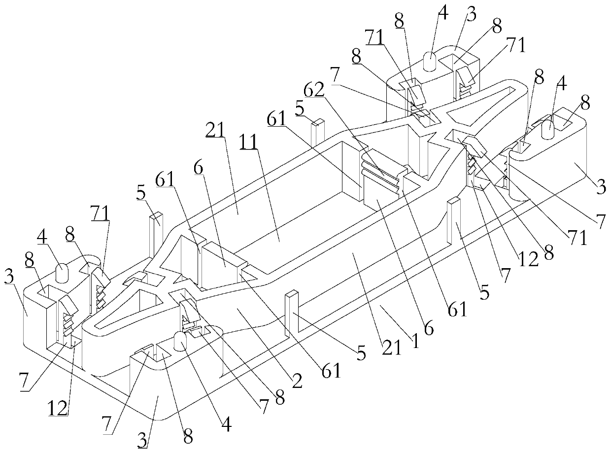
[0033] Such as figure 1 and figure 2 As shown, a wire harness isolator in this embodiment includes a spacer body 1 with a planar structure, and a through hole 11 is provided in the middle of the spacer body 1 for being sleeved on the internal structural member 9 of the battery pack. The middle part of the upper surface of the spacer body 1 is provided with a coaming plate 2, and the edge is provided with a limiting member 3. Two wire harness passages are defined, and the two wire harness passages are respectively located on both sides of the through hole 11 . Among them, the spacer body 1 of this embodiment is integrally formed and supported by an injection molding process, and the injection molded part has the properties of aging resistance, acid and alkali resistance, high temperature resistance, and salt spray resistance, which increases the safety of use.

[0034] In the wire harness spacer of this embodiment, by setting the body of the spacer, and setting a through hol...

Embodiment 2

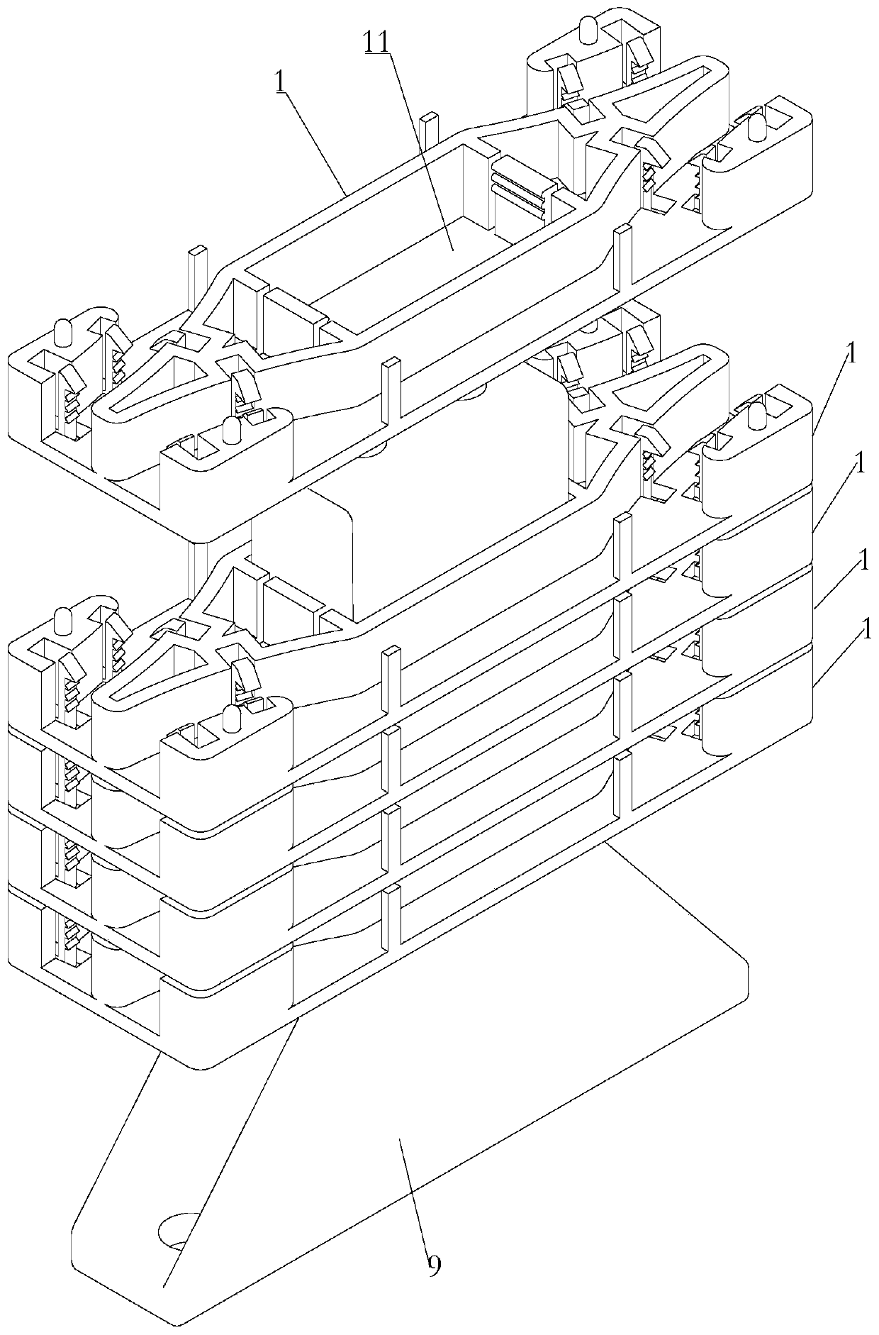
[0048] A battery pack in this embodiment includes a battery pack body, a structural member 9 and several wire harness spacers, the structural member 9 is installed in the battery pack body, and several spacer bodies 1 pass through the middle The through holes 11 are sleeved on the structural member 9 and arranged superimposedly.

[0049] Wherein, a preferred solution of this embodiment is that a two-layer module tray is arranged inside the battery pack body, the bottom of the structural member 9 is fixedly connected to the inner side of the battery pack body, and the top is fixedly connected to the two-layer module tray. The two sides of the structural member 9 are respectively provided with battery modules, and the spacer body 1 can be sleeved on the structural member 9, and the wiring harness channel on the spacer body 1 is used to isolate and clamp the wiring harness of each battery module and limit etc.

[0050] In the battery pack of this embodiment, the wiring harness i...


PUM


Abstract

The invention relates to a wire harness separator and a battery pack. The wire harness separator comprises a separator body with a flat plate structure, a through hole used for sleeving an inner structural member in a battery pack is formed in the middle of the separator body, surrounding plates are arranged in the middle of the upper surface of the separator body, limiting pieces are arranged atthe edge of the separator body, the surrounding plates are located on the periphery of the through hole, two wire harness channels are defined between the surrounding plates and the limiting pieces, and the two wire harness channels are located on the two sides of the through hole correspondingly. According to the wire harness separator, the separator body can be limited and arranged on the structural member in the battery pack through the through hole, wiring is carried out by utilizing the wire harness channels located on the two sides of the through hole in the separator body; and the flatstructure is adopted so that wire harnesses can be horizontally wired at interval along the separator body, the plurality of separator bodies can be stacked and used so that the multiple wire harnesses wires can be wired and separated from each other, matching is flexible, the cost is reduced, and the friction among the wire harnesses and the friction between the wire harnesses and the inner structural member of the battery pack can be effectively reduced.

Description

technical field [0001] The invention relates to the technical field related to new energy electric vehicles, in particular to a wire harness separator and a battery pack. Background technique [0002] Currently, the global auto industry is facing a huge adjustment in energy and environmental issues. Pure electric vehicles with high energy utilization and no pollution to the environment are increasingly becoming the direction of future automotive industry development. As the core component of electric vehicles, the safety of electric vehicle power batteries will directly affect the performance and driving safety of electric vehicles. The high-voltage electrical system undertakes the energy transmission task of the entire battery system, and its main function is to connect or disconnect the high-voltage circuit according to the control requirements of the vehicle; when the current of the power battery system is too large or the circuit is short-circuited, the high-voltage ele...

Claims


Application Information

Patent Timeline
Patent Type & Authority Applications(China)
IPC IPC(8): B60R16/02B60K1/04H02G3/02
CPCB60K1/04B60R16/0215H02G3/02
Inventor 柴成广
Owner BEIJING PRIDE NEW ENERGY BATTERY
Why Eureka
Try Eureka