Forming method of liquid rubber composite joint with inner groove flow channel and joint

A liquid rubber, liquid technology, applied in the direction of shock absorber-spring combination, shock absorber, spring, etc., can solve problems such as difficulty in realization, and achieve the effect of ensuring product quality, optimizing product performance, and large axial stiffness

Active Publication Date: 2019-11-08
ZHUZHOU TIMES RUIWEI ANTI VIBERATION EQUIP LTD
View PDF9 Cites 12 Cited by
  • Summary
  • Abstract
  • Description
  • Claims
  • Application Information

AI Technical Summary

Problems solved by technology

[0009] In order to further optimize the performance of liquid rubber composite joints, the product needs to provide greater axial stiffness and

Method used


Image

  • Forming method of liquid rubber composite joint with inner groove flow channel and joint
  • Forming method of liquid rubber composite joint with inner groove flow channel and joint
  • Forming method of liquid rubber composite joint with inner groove flow channel and joint

Examples


Embodiment 1

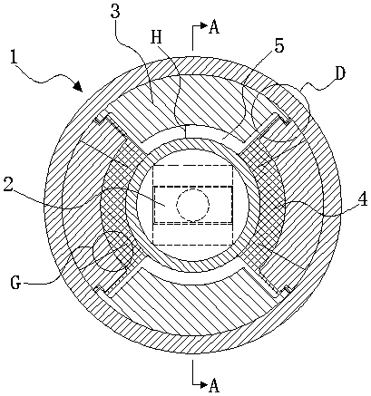
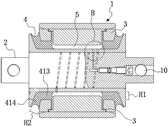
[0041] Embodiment 1: as figure 1 and figure 2 As shown, a method for forming a liquid rubber composite node with an inner groove flow path, which is to add an intermediate spacer 3 between the outer casing 1 and the mandrel 2, and bond the intermediate spacer 3 and the mandrel 2 through rubber 4 vulcanization. Connect together, and then assemble the integrated intermediate spacer and mandrel into the outer casing 1; set the inner groove flow channel in the mandrel 2, and hollow out multiple spaces on the middle spacer 3. After vulcanization, use The rubber 4 and the multiple spaces form a plurality of liquid cavities 5 that are independent of each other, and liquid (not shown in the figure) is arranged in the multiple liquid cavities 5, and the inner groove flow path is passed between the multiple liquid cavities 5 connected. The liquid rubber composite joint formed by the above method can provide smaller radial stiffness and greater axial stiffness, and achieve a larger dy...

Embodiment 2

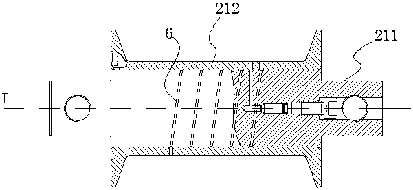
[0059] Embodiment 2: This embodiment mainly describes another end structure of the runner groove, such as Figure 12 As shown, compared with Embodiment 1, the difference lies in that the runner groove 6 of this embodiment adopts oblique end portions. The dynamic stiffness provided by the node with oblique end runner grooves is less than that provided by the node with right angle end runner grooves, and the inflection point of frequency increase is generally in the range of 2-4Hz.

Embodiment 3

[0060] Embodiment 3: This embodiment mainly describes another end structure of the runner groove, such as Figure 13 As shown, compared with Embodiment 1, the difference is that the runner groove of this embodiment adopts a closed end. One end of this type of runner groove includes a closing runner groove 1 613 , a closing runner groove 2 614 and a closing runner groove 3 615 connected in sequence, and the closing runner groove 1 613 is connected with a mandrel through hole 213 Pass, the third runner groove 615 of the closed mouth is connected with the middle runner groove of the spiral runner groove 6. The other end portion of this type of runner groove also includes a closed runner groove 1 613 , a closed runner groove 2 614 and a closed runner groove 3 615 connected in sequence, which will not be repeated here.

[0061] The groove width K3 of the closed runner groove 1 613 is greater than the groove width K4 of the closed runner groove 2 614, and the groove width K5 of the...


PUM


Abstract

The invention discloses a forming method of a liquid rubber composite joint with an inner groove flow channel and the joint. The forming method comprises the steps that a middle spacing sleeve is additionally arranged between an outer sleeve and a core shaft, the middle spacing sleeve and the core shaft are pasted together through rubber vulcanization, and the middle spacing sleeve and the core shaft which are integrated are assembled into the outer sleeve; and the inner groove flow passage is arranged in the core shaft, the middle spacing sleeve is hollowed out to form a plurality of spaces,after vulcanization is carried out, rubber and the multiple spaces form a plurality of independent liquid cavities, liquid exists in the multiple liquid cavities, and the multiple liquid cavities arein communication with each other through the inner groove flow channel. By means of the forming method and the joint, small radial stiffness and large axial stiffness can be provided, a large dynamicand static ratio is achieved, and the product performance of the liquid rubber composite joint is optimized.

Description

technical field [0001] The invention relates to a method for forming a liquid rubber composite node and a node product, in particular to a method for forming a liquid rubber composite node with an inner groove flow channel and the node. Background technique [0002] According to the dynamic requirements, when the pivoting arm node is running in a straight line at high speed (high frequency vibration), it provides a large radial stiffness to ensure the running stability and increase the critical speed; when it passes the curve (low frequency and large amplitude), it provides a small stiffness performance Guaranteed over-curve performance and reduced wear; it is difficult for ordinary joints to achieve the above characteristics, especially for old lines, where wheel rails and lines wear a lot, and the maintenance cost is high. Therefore, it is necessary to use a new product that has the above characteristics at the same time—liquid rubber composite joints. [0003] The working...

Claims


Application Information

Patent Timeline
IPC IPC(8): F16F13/18
CPCF16F13/18
Inventor 林胜陈俊辉张玉祥黄江彪李静曾先会罗俊张国青
Owner ZHUZHOU TIMES RUIWEI ANTI VIBERATION EQUIP LTD
Why Eureka
Try Eureka