Eureka AIR delivers breakthrough ideas for toughest innovation challenges, trusted by R&D personnel around the world.

Furnace wall structure of push plate furnace

A technology of pushing plate furnace and furnace wall, applied in furnace, furnace lining, furnace type, etc., can solve the problems of poor furnace wall density, high construction strength, slow masonry progress, etc., achieve reasonable furnace wall structure design, reduce masonry The effect of increasing the strength of construction work and increasing the density

Pending Publication Date: 2019-11-08
SUZHOU HUIKE EQUIP CO LTD
View PDF0 Cites 4 Cited by
  • Summary
  • Abstract
  • Description
  • Claims
  • Application Information

AI Technical Summary

Problems solved by technology

In the aforementioned furnace wall bricks, in order to reduce the joints on the left and right side walls of the furnace as much as possible to reflect the desired sealing, energy saving and long-term stability of the furnace body, etc., it is located on the left and right sides of the furnace. The side length of the furnace wall bricks on the opposite side of the furnace often reaches 500-600mm or more, and bricks made of high-temperature-resistant heavy materials are selected. And there are at least the following confusions in the masonry of the furnace wall bricks on the right: one is that the bricks are so bulky that the labor intensity of the masonry is so high that it is almost unbearable by his physical strength; The splicing density or airtightness between the bricks is difficult to meet expectations; the third is that the masonry progress is very slow due to the high construction intensity, which will significantly increase the manufacturing cost; The density is relatively poor. On the one hand, it is not conducive to saving energy consumption. On the other hand, it affects the overall quality of the furnace body to a certain extent.

Method used


Image

  • Furnace wall structure of push plate furnace
  • Furnace wall structure of push plate furnace

Examples


Embodiment Construction

[0020] In order to understand the technical essence and beneficial effects of the present invention more clearly, the applicant will describe in detail the following examples, but the descriptions of the examples are not intended to limit the solutions of the present invention. Equivalent transformations that are only formal but not substantive should be regarded as the scope of the technical solution of the present invention.

[0021] In the following descriptions, all concepts involving directionality or orientation of up, down, left, right, front and rear are based on the position state of the picture being described, more precisely figure 1 The shown position status is a reference, so it cannot be understood as a special limitation on the technical solution provided by the present invention.

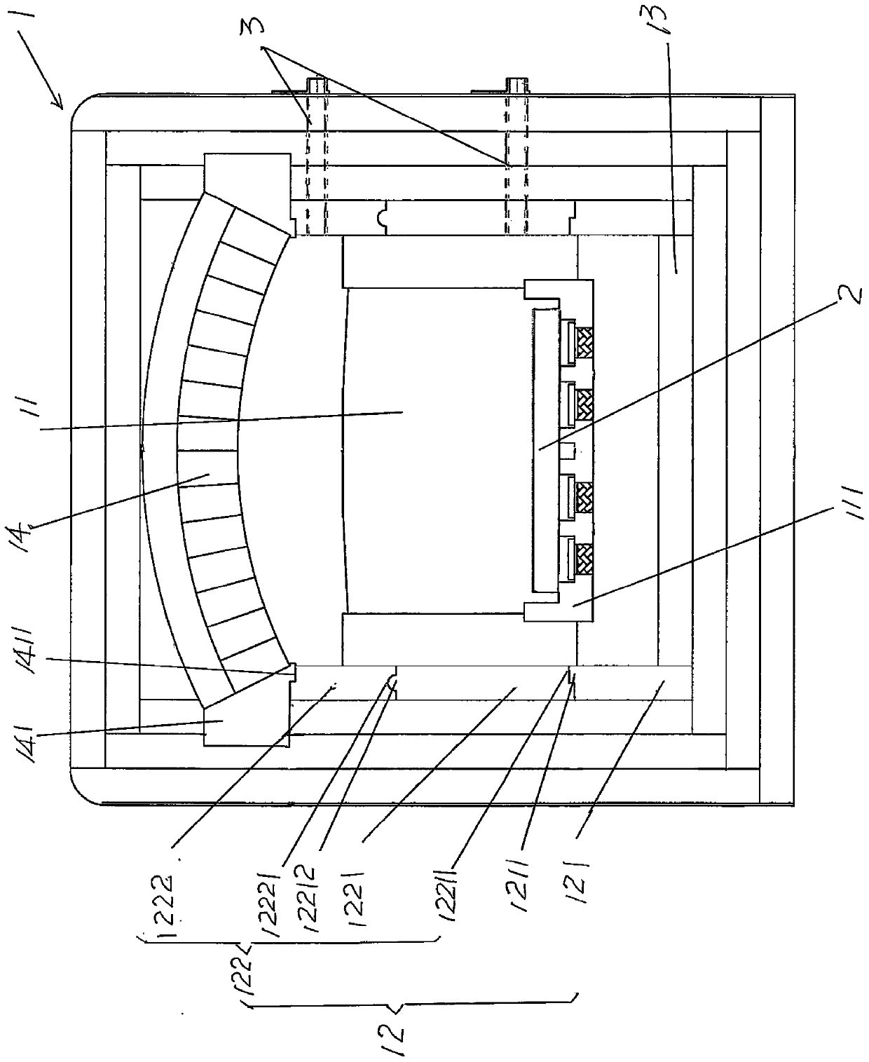
[0022] See figure 1 and figure 2 , shows a furnace body 1 of the structural system of the pusher furnace, and the central position of the furnace body 1 forms a furnace 11 penetra...


PUM


Abstract

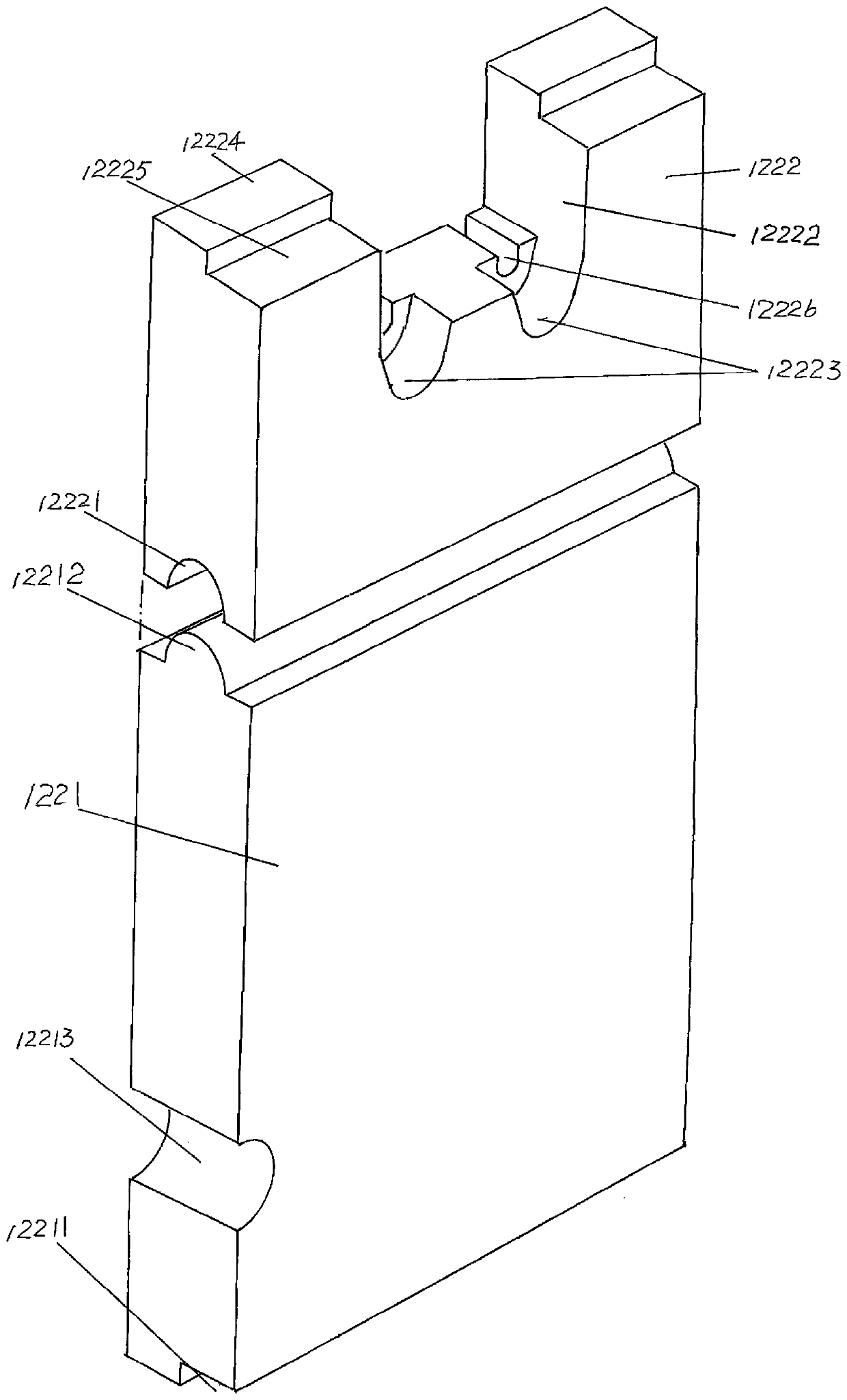
The invention provides a furnace wall structure of a push plate furnace, and belongs to the technical field of kiln facilities. The push plate furnace comprises a furnace body, there is a combustion chamber in the center of the furnace body, the furnace wall structure comprises a combustion chamber side wall body, and the combustion chamber side wall body comprises combustion chamber side wall upper bricks and combustion chamber side wall lower bricks. The furnace wall structure is characterized in that combustion chamber side wall lower brick matching bosses are constituted at the upper portions of the combustion chamber side wall lower bricks, the combustion chamber side wall upper bricks comprise combustion chamber side wall transition bricks and combustion chamber side wall top bricks,transition brick matching boss compensation cavities are arranged at the bottoms of the combustion chamber side wall transition bricks, combustion chamber side wall transition brick matching parts are arranged at the upper portions of the combustion chamber side wall transition bricks, combustion chamber side wall top brick matching parts are arranged at the lower portions of the combustion chamber side wall transition bricks, avoiding cavities are arranged on the sides, facing upwards, of the combustion chamber side wall top bricks, electrical heating rod bearing cavities are arranged at thebottoms of the avoiding cavities, and the side portions of combustion chamber top wall bricks are supported at the upper portions of the combustion chamber side wall upper bricks. The furnace wall structure has the advantages that masonry operation strength is reduced, good leakproofness at joints is ensured, the masonry construction speed is increased, the erection cost is reduced, and the energy-saving effect is ideal.

Description

technical field [0001] The invention belongs to the technical field of kiln facilities, and in particular relates to a furnace wall structure of a pusher furnace. Background technique [0002] The aforementioned push plate furnace is mainly used for electronic ceramics, special ceramics, alumina and zirconia ceramics, honeycomb ceramics, rare earths, magnetic materials, lithium battery cathode materials, chemical powders, tricolor phosphors, crystalline silicon photovoltaic cell materials, alumina Sintering of substrates and aluminum nitride substrates (customarily called "firing"). [0003] The push plate furnace is a continuous furnace, which is suitable for long-term uninterrupted continuous work. Non-powder and non-granular materials are placed on the push plate, typically such as the aforementioned alumina substrate and aluminum nitride substrate, etc. etc., if it is powder and granular material, then put it into a sagger or a crucible, which is carried by the sagger o...

Claims


Application Information

Patent Timeline
IPC IPC(8): F27B9/34F27D1/00F27D1/04
CPCF27B9/34F27D1/0006F27D1/045Y02P40/60
Inventor 陈龙豪金磊计晓铭朱从健
Owner SUZHOU HUIKE EQUIP CO LTD
Why Eureka
Eureka Blog
Learn More