A Three-pass Band Power Divider Filter Based on Multimode Fork Resonator

A resonator and filter technology, applied in resonators, waveguide-type devices, circuits, etc., can solve the problems that affect the wide application of power division filters, increase the difficulty of design and implementation, and difficult to pass band design requirements, and achieve good Effects of power distribution characteristics and filtering characteristics, good out-of-band rejection characteristics, and good port isolation characteristics

Active Publication Date: 2021-06-01
NANJING IND INST FOR ADVANCED INTELLIGENT EQUIP +1
View PDF2 Cites 0 Cited by
  • Summary
  • Abstract
  • Description
  • Claims
  • Application Information

AI Technical Summary

Problems solved by technology

However, due to the complex circuit structure and high port isolation, the problem of poor out-of-band rejection affects the wide application of this power divider filter.
[0004] Literature 2 [C.-F.Chen, T.-Y.Huang, and R.-B.Wu, "Novel compact net-typeresonators and their applications to microstrip bandpass filters," IEEETrans.Microw.Theory Techn., vol. 54, no.2, pp.755-762, Feb.2006] By using a mesh three-mode resonator, a multi-passband microstrip filter is realized simply and efficiently without significantly increasing the circuit size , however, due to the limitation of the degree of freedom of design parameters, it is difficult to realize the design requirements for all passbands at the same time, which increases the difficulty of design realization
[0005] Document 3 [R.Gómez-Garcia, R.Loeches-Sanchez, D.Psychogiou, and D.Peroulis, "Single / multi-band Wilkinson-type power dividers with embedded transversalfiltering sections and application to channelized filters," IEEETrans.Circuits Syst .I, Reg.Papers, vol.62, no.6, pp.1518-1527, Jun.2015.] proposed a new type of single / multiple passband Wilkinson power divider with inherent filtering capability, but its Large circuit size and poor port isolation

Method used


Image

  • A Three-pass Band Power Divider Filter Based on Multimode Fork Resonator
  • A Three-pass Band Power Divider Filter Based on Multimode Fork Resonator
  • A Three-pass Band Power Divider Filter Based on Multimode Fork Resonator

Examples


Embodiment Construction

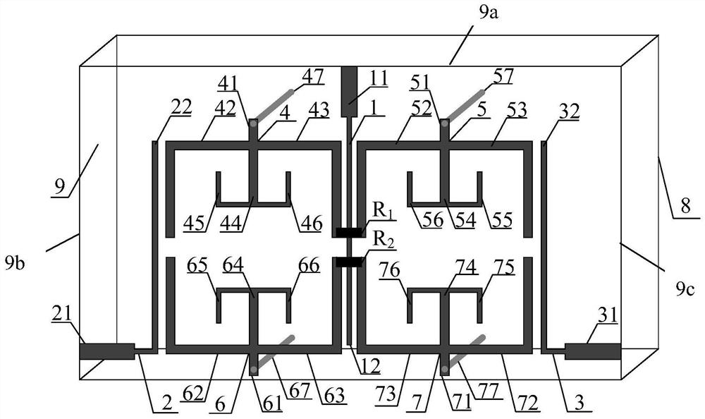
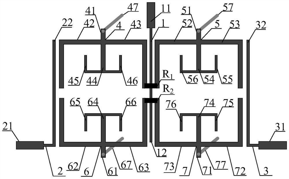
[0047] Examples such as figure 1 , the present embodiment provides a three-pass band power divider filter based on a multimode fork resonator, including a dielectric substrate 9, a metal ground plate 8 is provided on the bottom surface of the dielectric substrate 9, and an input port feeder 1, a second input port feeder is provided on the top surface An output feeder 2 and a second output feeder 3, the input port feeder 1 is located in the middle of the dielectric substrate 9, and the first output feeder 2 and the second output feeder 3 are respectively arranged symmetrically on both sides of the input port feeder 1;

[0048] A first fork-shaped three-mode resonator 4 and a second fork-shaped three-mode resonator 6 are respectively provided between the input port feeder 1 and the first output feeder 2;

[0049] A third fork-shaped three-mode resonator 5 and a fourth fork-shaped three-mode resonator 7 are respectively provided between the input port feeder 1 and the second outp...


PUM


Abstract

The invention discloses a three-pass band power dividing filter based on a multi-mode fork resonator, which comprises a dielectric substrate, a metal grounding plate is provided on the bottom surface of the dielectric substrate, and an input port feeder, a first output feeder and a second feeder are provided on the top surface. The output feeder, the input port feeder is located in the middle of the dielectric substrate, the first output feeder and the second output feeder are symmetrically arranged on both sides of the input port feeder; the input port feeder and the first output feeder are respectively provided with a first fork A three-mode fork resonator and a second fork-shaped three-mode resonator; a third fork-shaped three-mode resonator and a fourth fork-shaped three-mode resonator are respectively arranged between the input port feeder and the second output feeder.

Description

technical field [0001] The invention relates to the technical field of microwave passive devices, in particular to a three-pass band power dividing filter based on a multimode fork resonator. Background technique [0002] In modern wireless communication systems, power dividers and filters are important RF front-end passive components. In order to realize power distribution and filtering functions at the same time, they are often designed in the circuit in a cascaded manner. In this way, not only the circuit The volume will increase, and the circuit performance will decrease. Therefore, in order to reduce the size of the circuit and improve the performance of the circuit, the research of the power divider with filter response has been explored in recent years. At the same time, with the continuous development of modern wireless communication systems, the demand for multi-passband communication systems is also increased. [0003] Document 1 [K.J.Song, M.Y.Fan, and F.Zhang, ...

Claims


Application Information

Patent Timeline
Patent Type & Authority Patents(China)
IPC IPC(8): H01P1/203H01P7/08
CPCH01P1/20381H01P1/2039H01P7/082
Inventor 张钢张心德杨继全颜林峰
Owner NANJING IND INST FOR ADVANCED INTELLIGENT EQUIP
Why Eureka
Try Eureka