

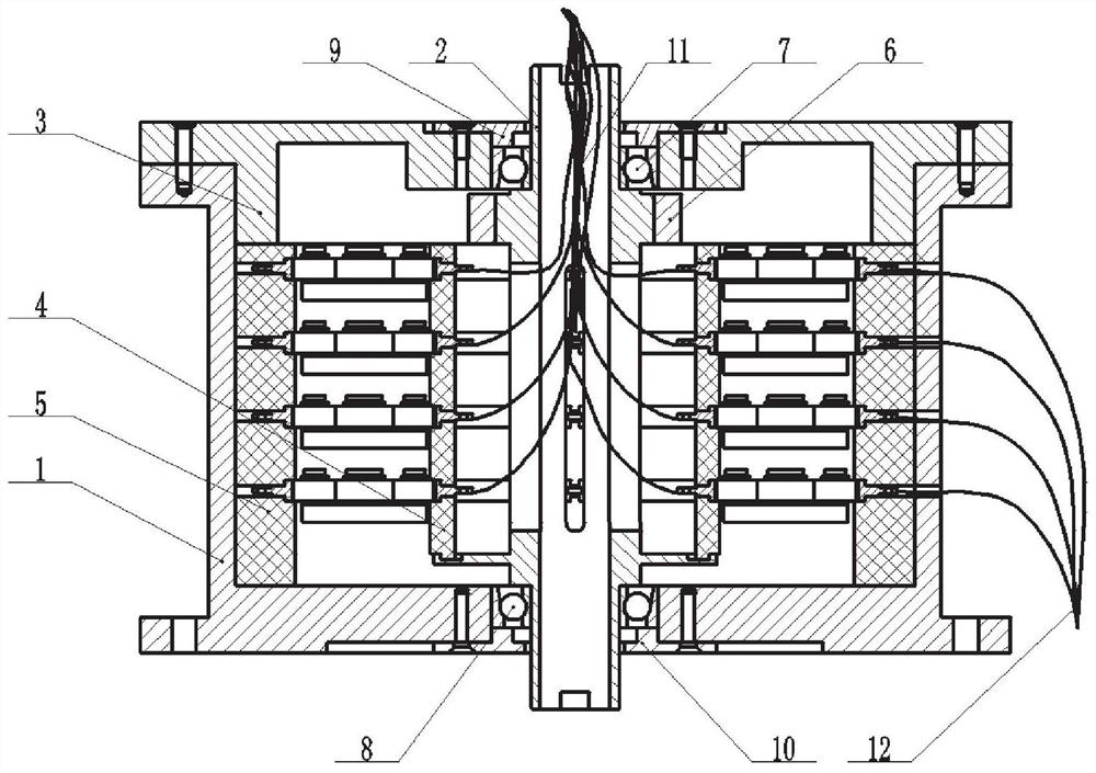
A rolling collector ring
A slip ring and rolling technology, applied in the direction of rotating current collectors, current collectors, electrical components, etc., can solve the problems of easy wear on the sliding contact surface, increase equipment maintenance costs, reduce the reliability of the slip ring, etc., and achieve low wear rate , suitable for high-power transmission, improving reliability and service life
- Summary
- Abstract
- Description
- Claims
- Application Information
AI Technical Summary
Problems solved by technology
Method used
Image

Examples
Embodiment Construction
[0023] The invention will be described in detail below in conjunction with specific embodiments. The following examples will help those skilled in the art to further understand the present invention, but do not limit the present invention in any form. It should be pointed out that for those of ordinary skill in the art, several changes and improvements can be made without departing from the concept of the present invention. These all belong to the protection scope of the present invention.
[0024] In the related art, according to the different contact friction modes, the catcher ring can be divided into a sliding friction catcher ring and a rolling friction catcher ring. The manufacturing technology of the sliding friction type bus ring is relatively mature and is widely used in various rotating interfaces. However, the sliding friction torque is large, the sliding contact surface is easy to wear, and the fluctuation resistance is large. This will greatly reduce the reliability...
PUM
 Abstract
Description
Claims
Application Information