Driving circuit and inverter power supply

A drive circuit and main drive technology, applied in the direction of adjusting electrical variables, high-efficiency power electronic conversion, electrical components, etc., can solve the problems of difficult matching of high pulse duty cycle, low operating frequency, long off time, etc.

Pending Publication Date: 2019-11-08
SHANGHAI HUGONG ELECTRIC WELDING MACHINE MFG
View PDF0 Cites 0 Cited by
  • Summary
  • Abstract
  • Description
  • Claims
  • Application Information

AI Technical Summary

Problems solved by technology

However, the high-voltage high-power IGBT has a long turn-off time and low operating frequency; when the active PFC technology is integrated into the inverter power supply, the operating frequency of the standard BOOST main circuit (also called a boost chopper) and The high pulse duty cycle of standard active PFC chips is difficult to match

Method used


Image

  • Driving circuit and inverter power supply
  • Driving circuit and inverter power supply
  • Driving circuit and inverter power supply

Examples


Embodiment Construction

[0041] The present invention will be further described in detail below with reference to the drawings and embodiments. It can be understood that the specific embodiments described here are only used to explain the present invention, but not to limit the present invention. In addition, it should be noted that, for ease of description, the drawings only show a part but not all of the structure related to the present invention.

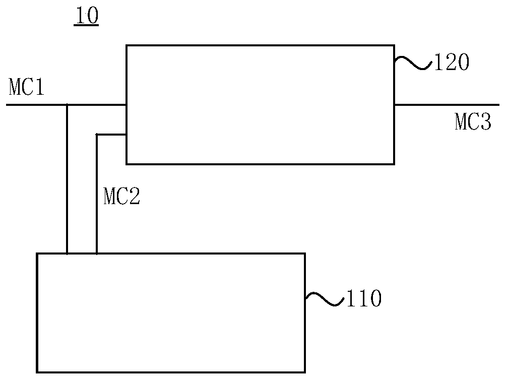
[0042] Exemplary, refer to figure 1 , The driving circuit 10 includes: a pulse width control module 110 and a main driving module 120; the pulse width control module 110 includes a pulse width signal input terminal and a pulse width signal output terminal, the main driving module 120 includes a first pulse signal input terminal, a second Pulse width signal input and output terminals; the pulse width signal input terminal of the pulse width control module 110 is electrically connected to the first pulse signal input terminal of the main drive module, and bot...


PUM


Abstract

The invention discloses a driving circuit and an inverter power supply. The driving circuit comprises a pulse width control module and a main driving module; a pulse width signal input end of the pulse width control module and a first pulse signal input end of the main driving module are electrically connected and are both used for receiving a first pulse signal; a pulse width signal output end ofthe pulse width control module is electrically connected with a second pulse width signal input end of the main driving module, and the pulse width control module converts the first pulse signal intoa second pulse signal and outputs the second pulse signal to the main driving module; the main driving module is used for generating a third pulse signal according to the first pulse signal and the second pulse signal, and the third pulse signal is output by the output end of the main driving module; the pulse width of the third pulse signal is determined by the first pulse signal and the secondpulse signal. According to the technical scheme provided by the embodiment of the invention, a driving signal (namely the third pulse signal) provided by the driving circuit for a BOOST main loop canbe matched with a working frequency of the BOOST main loop.

Description

Technical field [0001] The embodiment of the present invention relates to the technical field of inverter welding and cutting power supply control, in particular to a drive circuit and an inverter power supply. Background technique [0002] With the wide application of inverter welding and cutting power supplies, the current distortion problem caused by the inverter power supply to the power grid becomes more prominent. Active Power Factor Correction (PFC) technology is one of the most effective solutions. [0003] Generally, under the condition of high input grid voltage (such as 575Vac single-phase or three-phase grid voltage), the standard BOOST main loop output voltage can be designed to be as high as 950V or more +BUS voltage output. At this time, the power tube in the BOOST main loop needs to withstand voltage above 1200V; or use a complex topology to reduce the withstand voltage requirement of the power tube, so as to select a MOSFET or high-speed IGBT tube with a withstand ...

Claims


Application Information

Patent Timeline
Patent Type & Authority Applications(China)
IPC IPC(8): H02M1/08H02M1/42H02M3/00
CPCH02M1/08H02M1/42H02M3/00Y02B70/10
Inventor 不公告发明人
Owner SHANGHAI HUGONG ELECTRIC WELDING MACHINE MFG
Why Eureka
Try Eureka