Method and radar device for determining radial relative acceleration of at least one target

A technology of radar equipment and radial velocity, applied in the direction of using re-radiation, radio wave reflection/re-radiation, instruments, etc., can solve the problems of frequency difference, achieve the effect of compact implementation and simplification of further processing

Pending Publication Date: 2019-11-08
ROBERT BOSCH GMBH
View PDF8 Cites 3 Cited by
  • Summary
  • Abstract
  • Description
  • Claims
  • Application Information

AI Technical Summary

Problems solved by technology

Here, there is a frequency difference or delay between the t

Method used


Image

  • Method and radar device for determining radial relative acceleration of at least one target
  • Method and radar device for determining radial relative acceleration of at least one target
  • Method and radar device for determining radial relative acceleration of at least one target

Examples


Embodiment Construction

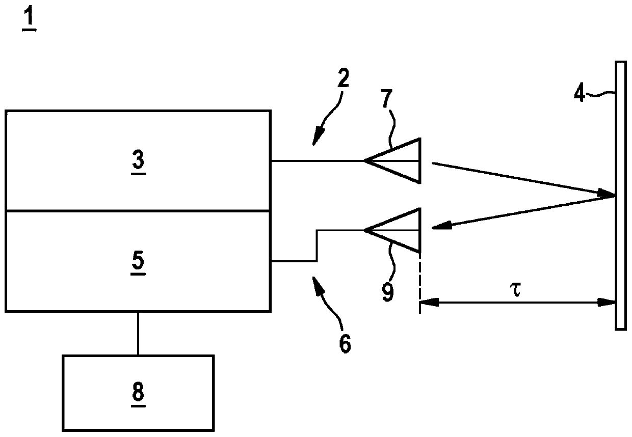
[0023] figure 1 A radar device 1 according to a first embodiment is shown. A plurality of radar waves are emitted by the transmitting device 2 as a ramp-FM radar transmission signal. The transmitting device 2 is composed of a transmitter 3 and a transmitting antenna 7 . The transmitter 3 operates a transmitting antenna 7 . According to this embodiment, fast chirp modulation is used. In the measurement interval not shown T 测量 During this period, M slope-shaped radar transmission signals modulated by short-wave frequency are sent. Here, the radar transmit signals have a time interval T from one another rr and has a corresponding duration T 调制 . The time interval T between the ramps rr It is of the same order of magnitude as the duration of the ramped or ramp-shaped frequency-modulated radar transmission. This time interval T rr Can be slightly larger or smaller than the ramp duration. The ramps can also be arranged unequally in time. The radar waves or radar transmis...


PUM


Abstract

The invention relates to a method for determining an acceleration of a target or an object by means of radar waves. In a first step, at least one radar-emitting signal is emitted by means of an emission device. At least one radar-receiving signal reflected by a target is received and subsequently transmitted to an evaluation unit. The evaluation unit converts the radar-receiving signals into digital measuring values and is used to further process the digital measuring values. In a further step, the digital measuring values are subjected to a two-dimensional Fourier transform. At least one target reflex is detected from a resulting magnitude spectrum or distance-speed spectrum, on the basis of peak values. Based on the distance-speed spectrum, at least one distance of a target from the emission device, at least one radial speed and at least one transverse speed of a target are determined in relation to the emission device. Subsequently, at least one angle of the at least one target is determined in relation to an orientation of the emission device. On the basis of the determination or calculation of the distance, the transverse speed and the angle, the signal portions respectively relevant to the estimation are separated. For at least one target reflex of an actual target or object, at least one radial acceleration is approximately calculated following an inverse Fourier transform of the remaining repeatedly transformed measuring values. The invention also relates to a radar device.

Description

technical field [0001] The invention relates to a method for ascertaining the acceleration of an object by means of radar waves, and also to a device for carrying out the method. Background technique [0002] Radar sensors or radar devices can be used in various vehicles to locate obstacles or other vehicles. This makes it possible, for example, to trigger a braking process automatically in the event of a collision risk. In addition, it is possible to assist the driver in maintaining the lane or keeping the distance from the vehicle ahead, supported by radar (for example by means of adaptive cruise control). Especially in the motor vehicle sector, radar devices can also be used to detect objects in blind spots and to warn the driver, for example, of a collision. [0003] In the radar system, the modulated transmission signal is transmitted via at least one transmission device. The transmitted signal is reflected by objects located within the transmission range. The refle...

Claims


Application Information

Patent Timeline
IPC IPC(8): G01S7/35G01S13/34G01S13/58
CPCG01S7/354G01S13/343G01S13/345G01S13/584G01S7/356G01S13/34
Inventor T·布罗舍
Owner ROBERT BOSCH GMBH
Why Eureka
Try Eureka