Eureka AIR delivers breakthrough ideas for toughest innovation challenges, trusted by R&D personnel around the world.

Pressurized oxygenerator

A technology of oxygen generator and air compressor, which is applied in the direction of inorganic chemistry, oxygen preparation, oxygen/ozone/oxide/hydroxide, etc., which can solve the problem that compressed air is not easy to absorb towers, the purity of oxygen generator equipment is reduced, and it is easy to wriggle Even problems such as pulverization, to achieve the effect of accelerating fluidity, simple structure, and reducing creep

Pending Publication Date: 2019-11-12
薛青
View PDF0 Cites 2 Cited by
  • Summary
  • Abstract
  • Description
  • Claims
  • Application Information

AI Technical Summary

Problems solved by technology

[0003] There are some defects in the current oxygen generator: First, a molecular sieve is mainly used in the adsorption tower for nitrogen adsorption. When the oxygen production rate is constant, the greater the output requirement, the greater the amount of molecular sieve, and the equipment design and selection are also difficult. The bigger it is, the compressed air will not be easy to fill the entire adsorption tower relatively evenly; the second is that after the compressed air enters the adsorption tower, it needs to pass through the gap between the molecular sieves, so that the pressure becomes less and less, which affects the efficiency of oxygen production; The third is that the purity of the obtained oxygen is generally around 90%, which is difficult to break through; the fourth is that after a long time of use, the molecular sieve is easy to wriggle or even pulverize, and the purity of the entire oxygen production equipment will decrease; fifth, after the molecular sieve absorbs nitrogen , desorb the molecular sieve simply by reducing the pressure, it is easy to cause incomplete desorption, and it is easy to accelerate the loss of the molecular sieve

Method used


Image

  • Pressurized oxygenerator
  • Pressurized oxygenerator
  • Pressurized oxygenerator

Examples


Embodiment Construction

[0022] The present invention will be further described below in combination with specific embodiments.

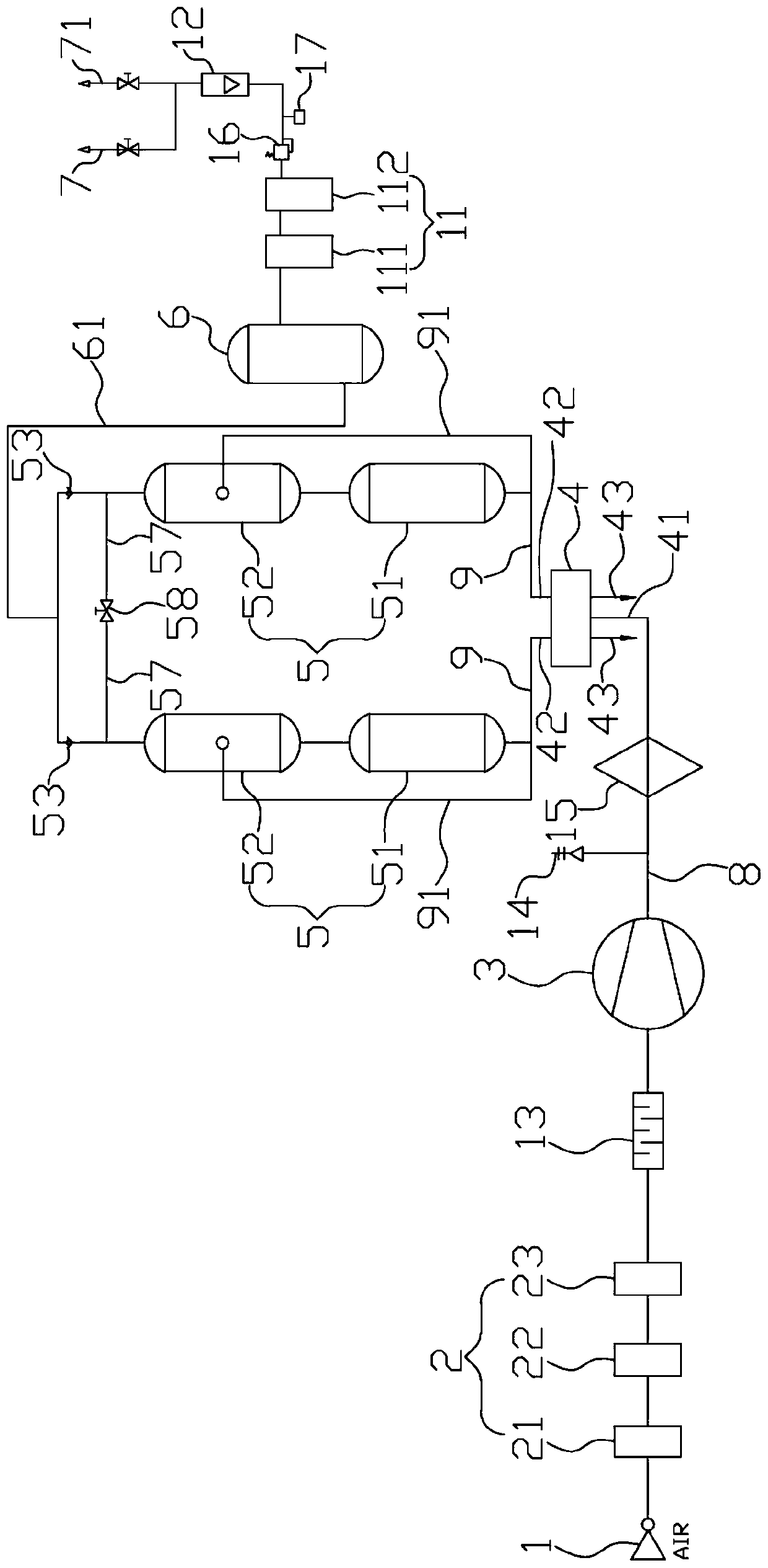
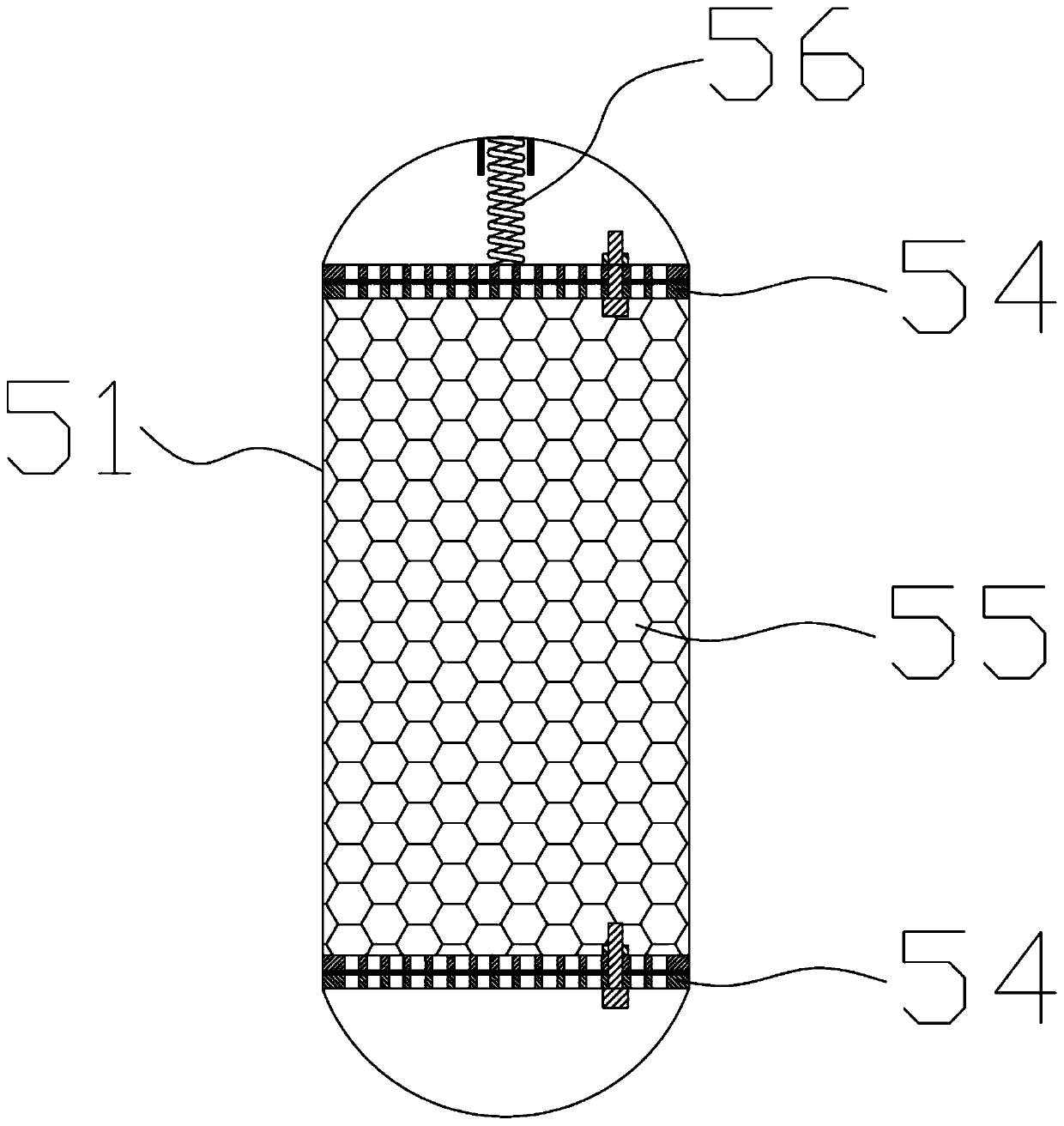
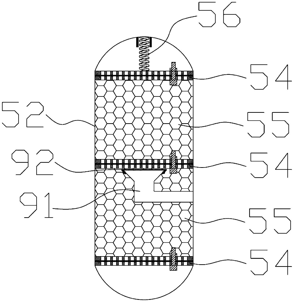
[0023] Such as figure 1 As shown, the pressurized oxygen concentrator according to one embodiment of the present invention includes an air inlet port 1, an air filter group 2, an air compressor 3, a solenoid valve 4, an adsorption tower group 5, an oxygen buffer tank 6 and oxygen Outlet pipeline 7. The air inlet end 1 is communicated with the inlet of the air filter group 2, the outlet of the air filter group 2 is communicated with the inlet of the air compressor 3, and the outlet of the air compressor 3 is communicated with the inlet of the solenoid valve 4 through the intake manifold 8. The air filter group 2 comprises the first air filter 21, the second air filter 22 and the third air filter 23 connected in sequence, and the air is dedusted, degreased and dried, at the outlet of the third air filter 23 and An intake muffler 13 is installed between the inlets of the air...


PUM


Abstract

The invention discloses a pressurized oxygenator. The pressurized oxygenator comprises an air inlet end, an air filter group, an air compressor, an electromagnetic valve, at least two groups of adsorption tower groups, an oxygen buffer tank and an oxygen outlet pipeline, wherein the air inlet end, the air filter group, the air compressor and the electromagnetic valve communicate with one another;each group of adsorption tower groups comprises a first molecular sieve tower and a second molecular sieve tower which communicate with each other, the first molecular sieve towers communicate with the electromagnetic valve through an air outlet total pipe, the second molecular sieve towers are provided with one-way valves, the middle parts of the second molecular sieve towers are connected with the air outlet total pipe through air outlet branched pipes, shunts are arranged at the upper ends and the lower ends of the first molecular sieve towers and the second molecular sieve towers, shunts are arranged above the air outlet branched pipes in the second molecular sieve towers, molecular sieves are arranged among the shunts in a filling mode, the one-way valves communicate with the oxygen buffer tank through an oxygen total pipe, and an outlet of the oxygen buffer tank is sequentially connected with the oxygen filter groups, a flowmeter and the oxygen outlet pipeline. According to the pressurized oxygenator, the continuity of oxygen generation is ensured and purity of prepared oxygen can be improved, the outlet branched pipes are connected into the second molecular sieve towers, andthe oxygen generation efficiency is improved.

Description

technical field [0001] The invention relates to the technical field of equipment for producing oxygen, and more specifically relates to a pressurized oxygen generator. Background technique [0002] The separated air of the industrial oxygen generator is mainly composed of two adsorption towers filled with molecular sieves. Under normal temperature conditions, the compressed air enters the adsorption tower after being purified by filtration and water removal. In the adsorption tower, the nitrogen in the air is absorbed by the molecular sieve Oxygen is enriched in the gas phase and stored in the oxygen buffer tank from the outlet, while the molecular sieve that has been adsorbed in the other tower is quickly depressurized to analyze the adsorbed components, and the two towers circulate alternately. Cheap oxygen with a purity of about 90% can be obtained. [0003] There are some defects in the current oxygen generator: First, a molecular sieve is mainly used for nitrogen adsor...

Claims


Application Information

Patent Timeline
Patent Type & Authority Applications(China)
IPC IPC(8): B01D53/04B01D46/00C01B13/02
CPCB01D53/04C01B13/0259C01B2210/0046C01B2210/0098B01D2253/10B01D46/64
Inventor 薛青薛超
Owner 薛青
Why Eureka
Eureka Blog
Learn More