
Adjustable feeding mechanism of numerical control machine tool

A CNC machine tool, adjustable technology, applied in metal processing and other directions, can solve the problems of material blockage, jamming, lack of guide parts in the feeding pipe, etc., and achieve the effect of accelerating the discharge speed

Active Publication Date: 2019-11-12
江门市江海区凯裕五金制品有限责任公司
View PDF12 Cites 0 Cited by
  • Summary
  • Abstract
  • Description
  • Claims
  • Application Information

AI Technical Summary

Problems solved by technology

[0005] In order to solve the above-mentioned technical problems, the present invention provides an adjustable feeding mechanism of a numerically controlled machine tool to solve the problem that most of the discharge pipes of the existing disc-type feed cabins installed on the numerically controlled machine tool are single-structured discharge pipes. This pipe guides the product materials ejected from the disc feed cabin to the processing station of the CNC machine tool. Since the feed pipe with a single structure lacks guiding parts, some cylindrical product materials are thus During the process of pipe fittings being discharged outward, there may be a phenomenon of jamming, and the material is stuck on the discharge pipe in a staggered manner, resulting in material blockage.

Method used


Image

  • Adjustable feeding mechanism of numerical control machine tool
  • Adjustable feeding mechanism of numerical control machine tool
  • Adjustable feeding mechanism of numerical control machine tool

Examples


Embodiment

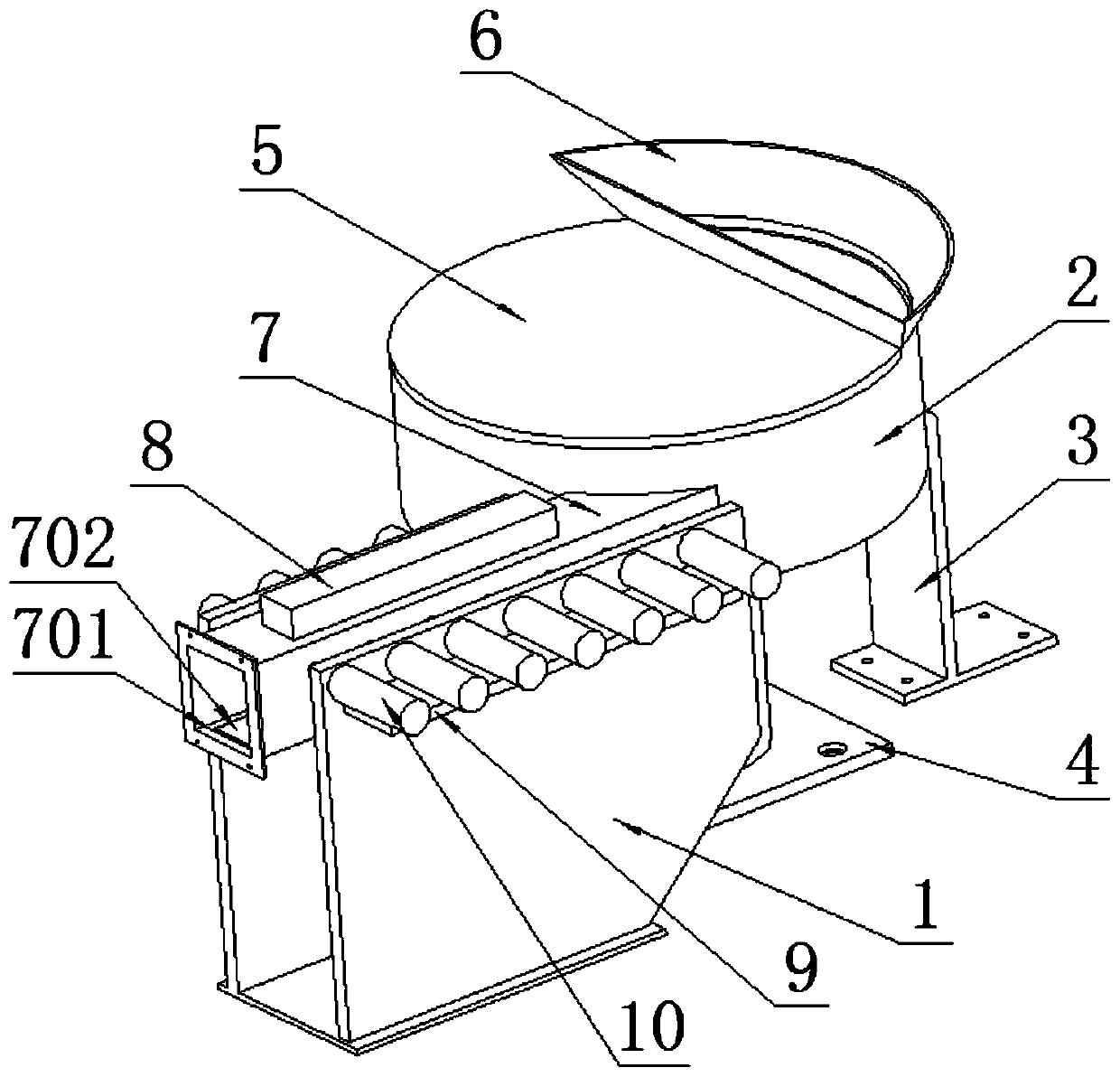
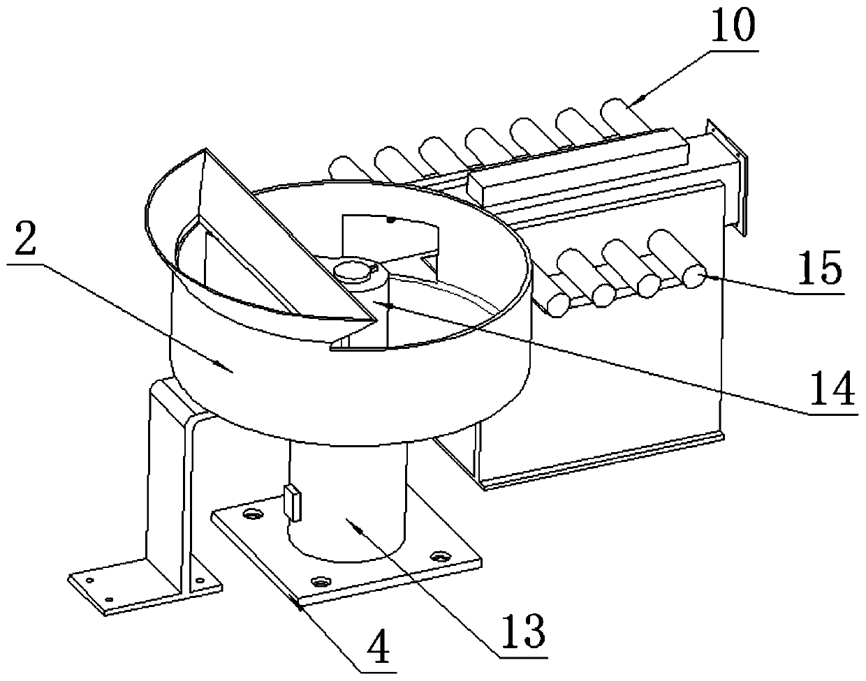
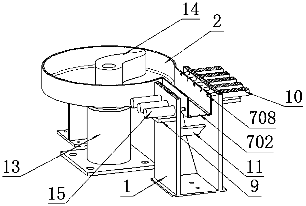
[0032] as attached figure 1 to the attached Figure 10 shown:

[0033] The present invention provides an adjustable feeding mechanism of a numerically controlled machine tool, including a vertical plate 1, a disc-shaped cabin 2, a vertical frame 3, a mounting plate 4, a cabin plate 5, a feeding port 6, a discharging pipe 7, a reserved groove 701, The first accessory plate 702, the second accessory plate 703, the shading 704, the top seat 706, the U-shaped clamp seat 707, the perforation 708, the power seat 8, the fixing plate 9, the right electric cylinder 10, the welding plate 11, the middle electric cylinder 12. The rotary motor 13, the material stopper 14 and the left electric cylinder 15; the vertical plate 1 is left and right, and their inner regions are jointly welded with a rectangular plate structure welding plate 11 in a backward inclined manner. A middle electric cylinder 12 is installed in the middle of the welding plate 11; the rotary motor 13 is installed on the...


PUM


Abstract

The invention provides an adjustable feeding mechanism of a numerical control machine tool. The adjustable feeding mechanism comprises a rotary motor, a material blocking part and a left part electriccylinder, a left vertical plate and a right vertical plate are arranged, a welding plate with a rectangular plate structure is welded on the inner side regions of the vertical plates in a backwards inclined mode, and a middle electric cylinder is further arranged in the middle position of the welding plate; the rotary motor is installed at the portion, at an existing numerical control equipment feeding area, of the surface of a machine body through a mounting plate, a disc-shaped cabin is matched with a power output shaft of the rotary motor, through a notch, the bottom surface of a pipe cavity of a discharging pipe is provided with discharging sliding surfaces of double mode structures, specifically, for spherical easy-to-discharge workpieces, the first type of steel plate type bottom surface accessory plate can be applied, for discharging of slightly-complex-structure workpieces, the second type of rubber corrugated plate type accessory plate can be applied, and when the second typeof plate is applied, the electric cylinder is arranged at the bottom so that fluctuant actions of the second type of plate can be formed, and the discharging speed of this type of material is accelerated, so that the bottom surface of the discharging pipe has an adjustable characteristic.

Description

technical field [0001] The invention belongs to the technical field of the feeding mechanism structure of a numerically controlled machine tool, and more particularly, particularly relates to an adjustable feeding mechanism of a numerically controlled machine tool. Background technique [0002] CNC machine tool is the abbreviation of digital control machine tool, which is an automatic machine tool equipped with a program control system. The control system can logically process the program specified by the control code or other symbolic instructions, decode it, represent it with coded numbers, and input it into the numerical control device through the information carrier. After arithmetic processing, various control signals are sent by the numerical control device to control the action of the machine tool, and the parts are automatically processed according to the shape and size required by the drawing. The feeding mechanism of the CNC machine tool is also relatively advance...

Claims


Application Information

Patent Timeline
IPC IPC(8): B23Q7/00
CPCB23Q7/00
Inventor 王亚琼
Owner 江门市江海区凯裕五金制品有限责任公司
Learn More