Eureka AIR delivers breakthrough ideas for toughest innovation challenges, trusted by R&D personnel around the world.

Automatic feeding device and control method for buzzer dispensing

A technology of automatic feeding and buzzer, which is used in conveyor control devices, devices for coating liquid on surfaces, vibrating conveyors, etc., which can solve the problem of unreasonable structure, affecting the dispensing effect, and inaccurate docking of positioning devices, etc. question

Pending Publication Date: 2019-11-12
江苏安澜万锦电子股份有限公司
View PDF0 Cites 2 Cited by
  • Summary
  • Abstract
  • Description
  • Claims
  • Application Information

AI Technical Summary

Problems solved by technology

[0005] Before the dispensing operation, the buzzer needs to be transported to the dispensing position by an external mechanism. However, the structure of the existing automatic feeding device is unreasonable, and the connection with the positioning device is not accurate enough, which affects the subsequent dispensing work. At the same time, The buzzer cannot be effectively positioned during the dispensing process, which further affects the dispensing effect

Method used

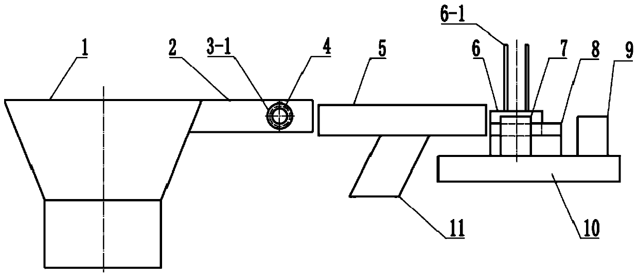
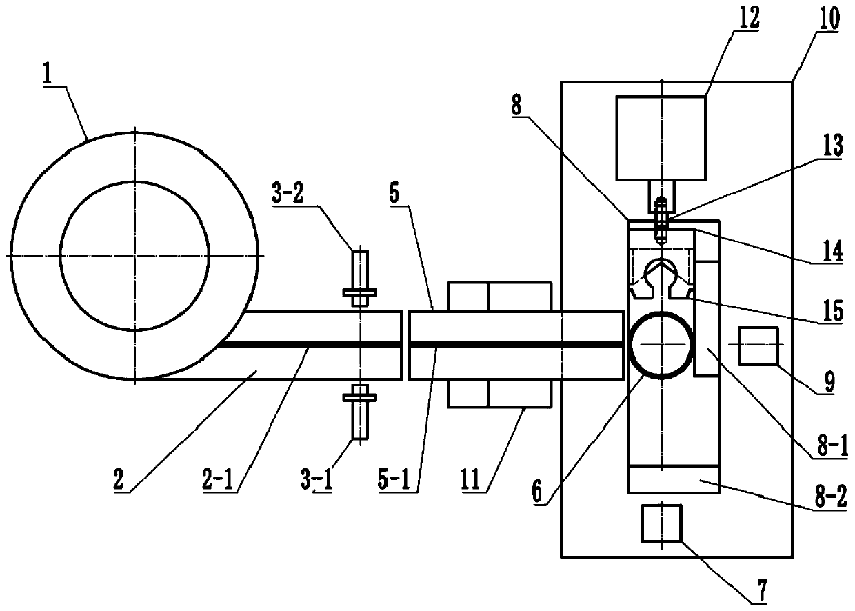
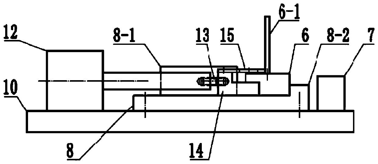

Image

  • Automatic feeding device and control method for buzzer dispensing
  • Automatic feeding device and control method for buzzer dispensing
  • Automatic feeding device and control method for buzzer dispensing

Examples


Embodiment Construction

[0029] The present invention will be described in further detail below in conjunction with the accompanying drawings.

[0030] A buzzer dispensing automatic feeding device of the present invention such as figure 1 , figure 2 , image 3 As shown, the first feeding guide rail 2 is welded to the outlet of the spiral track of the vibrating plate 1, and can vibrate together with the vibrating plate 1. The first feeding guide rail 2 outlet is equipped with an opposite-beam optical fiber sensor 3, wherein the transmitting end 3-1 and the receiving end 3-2 are respectively installed on both sides of the first feeding guide rail 2 outlet, and the first feeding guide rail 2 exits. The feed port is processed with a light hole 4 at the axis passing position of the transmitting end 3-1 and the receiving end 3-2, and the light emitted by the emitting end 3-1 can be irradiated to the receiving end 3-2 through the light hole 4.

[0031] The second feeding guide rail 5 is installed on the ...


PUM


Abstract

The invention discloses an automatic feeding device and control method for buzzer dispensing. The device comprises a vibration conveying device and a dispensing positioning device. The vibration conveying device comprises a vibration plate, a first feeding guide rail, a second feeding guide rail and a direct vibration device. A first positioning convex strip and a second reflective photoelectric sensor are arranged on the side, in the direction opposite to the conveying direction of the second feeding guide rail, on a dispensing platform. A push mechanism is arranged at the end, in the direction perpendicular to the conveying direction of the second feeding guide rail, on the dispensing platform, and a second positioning convex strip and a first reflective photoelectric sensor are arrangedat the other end of the dispensing platform. By the adoption of the automatic feeding device for buzzer dispensing, whether the number of workpieces in the second feeding guide rail reaches the fullcapacity or not is judged according to a signal of an opposite-type optical fiber sensor, and the vibration disc is controlled to stop vibrating. When the number of workpieces in the second feeding guide rail reaches the set lower limit value, the vibrating plate is started, so that the continuity of the feeding is ensured, the vibration time of the vibrating plate is shortened, the energy is saved, the starting and stopping frequency of the vibrating plate is reduced, and the service life of the vibrating plate is prolonged.

Description

technical field [0001] The invention relates to an automatic feeding device and a control method, in particular to an automatic feeding device and a control method suitable for buzzer dispensing. Background technique [0002] The buzzer is an electronic sounder with an integrated structure. It is powered by DC voltage and is widely used as a sounding device in electronic products such as computers, printers, copiers, alarms, electronic toys, automotive electronic equipment, telephones, and timers. . Buzzers are mainly divided into two types: piezoelectric buzzers and electromagnetic buzzers. [0003] The sounding principle of the buzzer is composed of a vibration device and a resonance device, and the buzzer is divided into a passive self-excited type and an active self-excited type. The working and sounding principle of the passive separately excited buzzer is: the square wave signal is input into the resonance device and converted into the sound signal output; the workin...

Claims


Application Information

Patent Timeline
IPC IPC(8): B65G27/02B65G27/04B65G43/08B05C13/02B05C11/10
CPCB65G27/02B65G27/04B65G43/08B05C13/02B05C11/1015B65G2203/044
Inventor 丁仕燕梁建锋杨小斌刘要许梁君
Owner 江苏安澜万锦电子股份有限公司
Why Eureka
Eureka Blog
Learn More