Integrated micro heading machine pushing system with screw drive and working method of integrated micro heading machine pushing system

A technology of screw drive and roadheader, which is applied in the direction of earthwork drilling, mining equipment, tunnels, etc., and can solve the problems of high strength requirements for the bearing wall of the launch shaft, heavy workload of equipment transfer and disassembly, and high production and construction costs. , to achieve the effect of convenient equipment transfer, simple structure and high work efficiency

Pending Publication Date: 2019-11-12
江苏马超地下工程设备有限公司
View PDF0 Cites 6 Cited by
  • Summary
  • Abstract
  • Description
  • Claims
  • Application Information

AI Technical Summary

Problems solved by technology

[0004] The above tunneling system has the following disadvantages: 1. The strength requirements for the bearing wall of the launching shaft are relatively high, and the production and construction costs are relatively high
2. The jacking system can only advance one cylinder stroke at a time, and the pushing stroke is quite limited after adding the top iron
3. When power supply is inconvenient for field construction, the cost of power transmission can only be increased, or additional generator sets can be purchased
4. The current construction method can only use the mud flushing method for slag removal, and the cost of a mud system is very high
5. The rotation of the cutter head is provided by the motor or hydraulic motor installed inside the shield body. When the cement pipe joint needs to be installed in each stroke, the motor cable or the motor oil pipe needs to be disconnected, and the new pipe joint needs to be crossed again. The process is relatively complicated, and when the tunnel is long, the construction time will be delayed for a long time
6. When encountering cracks in geological rocks, the loss of mud is large
7. The workload of equipment transfer and disassembly is heavy

Method used


Image

  • Integrated micro heading machine pushing system with screw drive and working method of integrated micro heading machine pushing system
  • Integrated micro heading machine pushing system with screw drive and working method of integrated micro heading machine pushing system
  • Integrated micro heading machine pushing system with screw drive and working method of integrated micro heading machine pushing system

Examples


Embodiment Construction

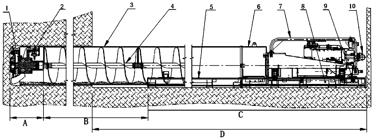
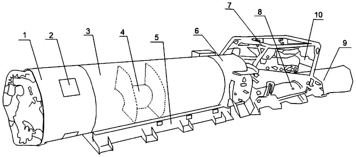
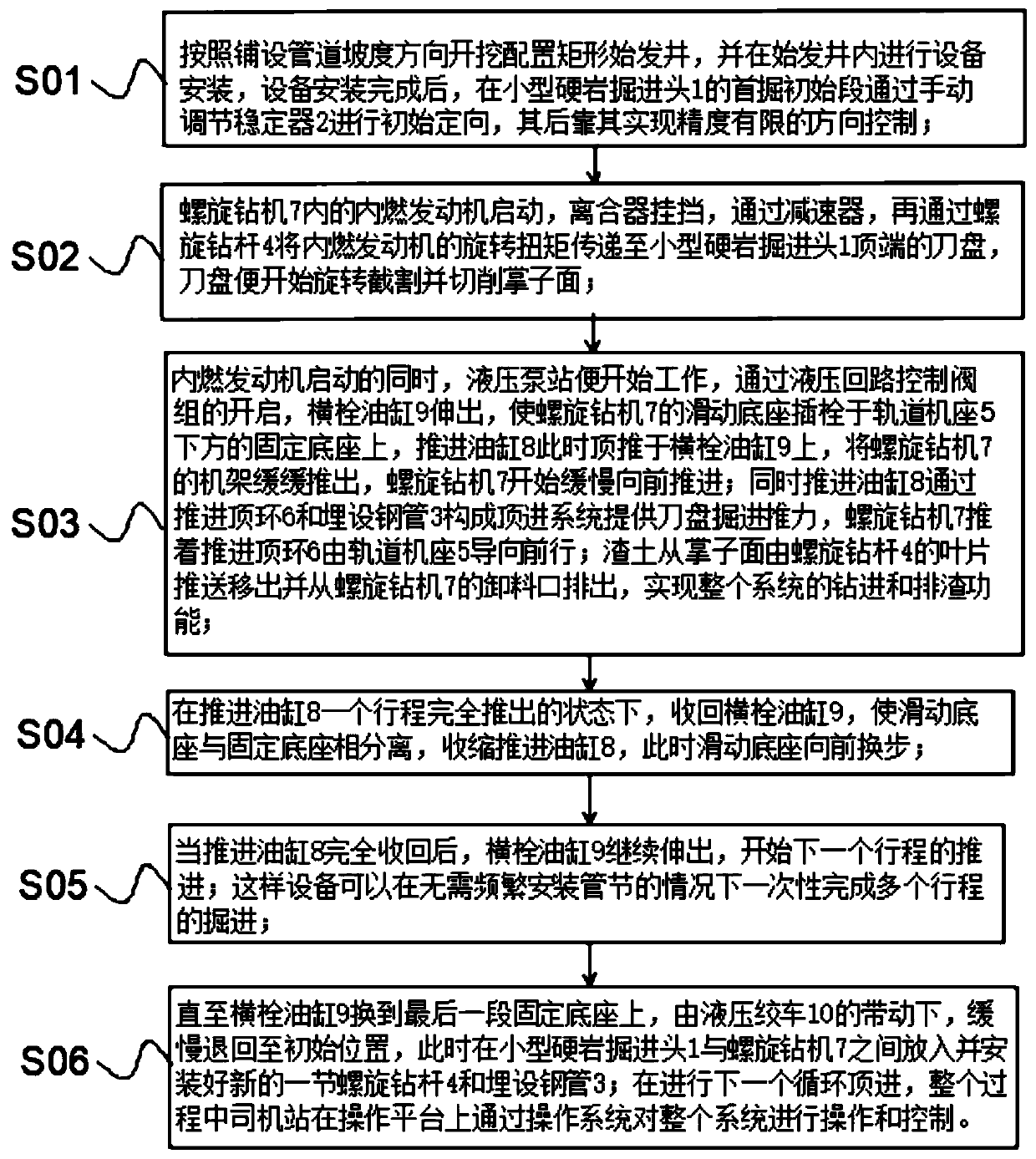
[0037] The following will clearly and completely describe the technical solutions in the embodiments of the present invention with reference to the accompanying drawings in the embodiments of the present invention. Obviously, the described embodiments are only some, not all, embodiments of the present invention. Based on the embodiments of the present invention, all other embodiments obtained by persons of ordinary skill in the art without creative efforts fall within the protection scope of the present invention.

[0038]In the description of the present invention, it should be understood that the terms "inner", "front end", "rear end", "both sides", "outer side", "side" etc. indicate orientation or positional relationship, and are only for the purpose of It is convenient to describe the present invention and simplify the description, but does not indicate or imply that the components or elements referred to must have a specific orientation, be constructed and operate in a spe...


PUM


Abstract

The invention discloses an integrated micro heading machine pushing system with screw drive and a working method of the integrated micro heading machine pushing system, and relates to the field of heading machine. The integrated micro heading machine pushing system with the screw drive comprises a track machine seat, a thrust oil cylinder, a buried pipeline, a micro hard rock heading head, a screwdrilling machine, a screw drill pipe, a thrust ejecting ring, a horizontal pin oil cylinder and a hydraulic winch; a sliding base in sliding fit with the track machine seat is arranged at the bottomof a machine frame of the screw drilling machine; a stabilizer is arranged on the outer side part of the micro hard rock heading head; and the buried pipe sleeves the screw drill pipe in a connectingmode. According to the integrated micro heading machine pushing system with the screw drive, the pushing system is integrated into mechanical equipment, an engine is used as a power source to simultaneously meet power of rotation of a cutter and power of the whole machine thrust, a screw rod device is used for discharging excavated muck, and a slurry system is eliminated for the whole traditionalmicro heading machine system; and the construction cost is reduced, the construction process is simplified, the heading speed of the micro heading machine is improved, and the construction work periodis shortened.

Description

technical field [0001] The invention belongs to the field of roadheaders, and in particular relates to an integrated miniature roadheader jacking system with a screw drive and a working method of the integrated miniature roadheader jacking system with a screw drive. Background technique [0002] For micro-tunnels below 2 meters, the main representative of the current equipment construction is the micro-heading machine or tunnel jacking machine. The working principle of this type of roadheader is that the rotation of the cutter head is realized by a motor or hydraulic motor and a gearbox installed in the shield body, and the advancement of the roadheader needs to be realized through the cylinder propulsion system. The muck excavated in front of the cutter head is stirred by continuously injecting special mud, and then the muck and mud are pumped out by the mud pump. [0003] At present, most manufacturers only supply the cutter head and front shield system, but the propulsio...

Claims


Application Information

Patent Timeline
Patent Type & Authority Applications(China)
IPC IPC(8): E21D9/08E21D9/093E21D9/12
CPCE21D9/08E21D9/093E21D9/12E21D9/124
Inventor 贺勇汤恩慧
Owner 江苏马超地下工程设备有限公司
Why Eureka
Try Eureka