Heat pipe type heat exchanger

A heat exchanger and heat pipe technology, applied in the field of heat exchanger devices, can solve the problems of uneven fuel combustion and heat exchange, small heat exchange coefficient between gas and high temperature heat exchanger, etc.

Inactive Publication Date: 2019-11-12
TECHNICAL INST OF PHYSICS & CHEMISTRY - CHINESE ACAD OF SCI
View PDF7 Cites 1 Cited by
  • Summary
  • Abstract
  • Description
  • Claims
  • Application Information

AI Technical Summary

Problems solved by technology

[0007] In order to solve the problems of uneven fuel combustion and heat transfer and small heat transfer coefficient between gas and high-temperature heat exchanger in the current power plant driven by heat transfer of heat pipe, the present invention provides a heat pipe heat exchanger, comprising: porous medium Material, integrated heat pipe and high-temperature heat exchanger; the integrated heat pipe includes a heat pipe condensation section, a heat pipe insulation section and a heat pipe evaporation section connected in sequence; the heat pipe evaporation section is embedded in a porous medium material, and the heat pipe condensation section is embedded in a high-temperature heat exchanger

Method used


Image

  • Heat pipe type heat exchanger
  • Heat pipe type heat exchanger
  • Heat pipe type heat exchanger

Examples


Embodiment 1

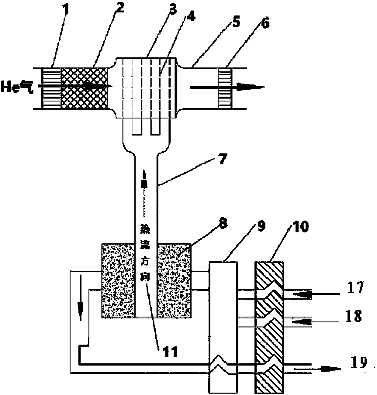
[0059] figure 2 It is a structural schematic diagram of a high temperature heat exchanger according to a preferred embodiment of the present invention,

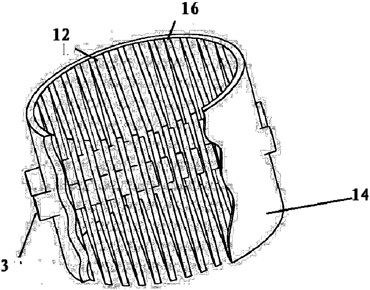
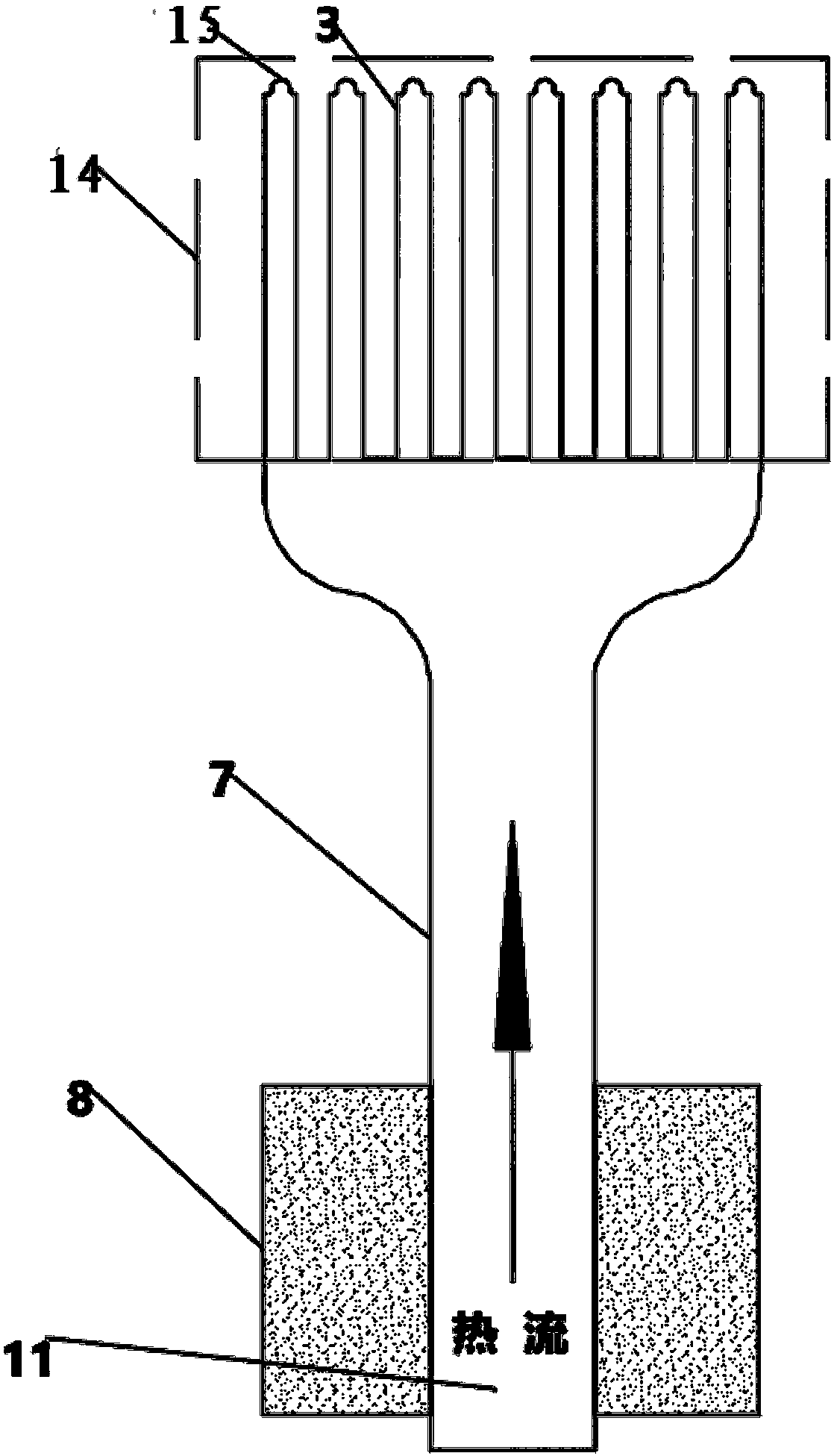
[0060] image 3 It is a schematic diagram of an integrated heat pipe according to a preferred embodiment of the present invention, such as figure 2 and image 3 As shown, the structure of this embodiment adopts a linear integrated heat pipe, which mainly includes a heat pipe condensation section 3, a heat pipe insulation section 7, a porous medium material 8, a heat pipe evaporation section 11, a high-temperature heat exchanger shell 14 and a gas collection bubble 15 compositions. This structure unifies the traditional multiple heat pipes discharged in parallel into a linear one-piece fork row structure. The heat pipes of this structure share the same heat pipe evaporation section 11, heat pipe insulation section 7 and heat pipe condensation section 3 respectively. Structures such as the heat-absorbing core in the conde...

Embodiment 2

[0063] Figure 4 It is a structural schematic diagram of a high temperature heat exchanger according to a preferred embodiment of the present invention,

[0064] Figure 5 It is a schematic diagram of an integrated heat pipe according to a preferred embodiment of the present invention, such as Figure 4 and Figure 5 As shown, the structure of this embodiment adopts an L-shaped integrated heat pipe, which consists of a heat pipe condensation section 3, a heat pipe insulation section 7, a porous medium material 8, a heat pipe evaporation section 11, a high-temperature heat exchanger shell 14, and a gas collection bubble 15 Composed of gas working medium heat exchange tubes 13. This structure respectively shares the same heat pipe evaporation section 11 , heat pipe insulation section 7 and heat pipe condensation section 3 . On the condensing section 3 of the heat pipe, the gas working medium heat exchange tubes 13 vertically inserted into the equidistant fork row, and the ma...

Embodiment 3

[0066] Figure 6 It is a schematic diagram of an integrated heat pipe according to a preferred embodiment of the present invention, such as Figure 6 As shown, the structure of this embodiment adopts an annular integrated heat pipe. The liquid working medium passes through the heat pipe evaporation section 11 after burning in the porous medium in the burner, and rises along the heat pipe adiabatic section 7 to enter the high-temperature heat exchanger of the thermoacoustic engine, and flows back to the burner along the annular heat pipe after condensing in the high-temperature heat exchanger , forming a flow loop. The inert gas working medium of the thermoacoustic engine flows through the high-temperature heat exchanger, and exchanges heat with the gaseous sodium-potassium alloy through the tube wall. When in use, the annular heat pipe obtains heat from a high-temperature heat source. In the condensation section 3 of the heat pipe, the steam in the heat pipe condenses and re...


PUM


Abstract

The invention provides a heat pipe type heat exchanger. Theheat pipe type heat exchanger comprises a porous medium material, an integrated heat pipe and a high-temperature heat exchanger, wherein theintegrated heat pipe comprises a heat pipe condensation section, a heat pipe heat insulation section and a heat pipe evaporation section which are connected in sequence, the heat pipe evaporation section is embedded in the porous medium material, and the heat pipe condensation section is embedded into the high-temperature heat exchanger. According to the heat exchanger, gas and air are mixed and burnt in the porous medium material, so that the heat exchange surface area is expanded by flue gas and the porous medium material, the heat transfer effect is enhanced, and the heat exchange coefficient is improved; and meanwhile, theintegrated heat exchange pipe is adopted, and high-temperature heat is uniformly conveyed into a heater of a power device, so that the high-efficiency, high-temperature and uniform heat exchange process of fuel in the power device is realized, the problems that a heating pipe is prone to being burnt out and heat exchange is difficult to strengthen due to the factthat at present, an engine is heated by directly utilizing the high-temperature flue gas are solved, and the later assembly and installation are facilitated.

Description

technical field [0001] The invention relates to the field of heat exchanger devices, in particular to a heat pipe heat exchanger and a power device comprising the heat pipe heat exchanger. Background technique [0002] The thermoacoustic effect is a physical phenomenon in which heat induces acoustic self-excited oscillations in elastic media that are mainly high-pressure inert gases. Utilizing the thermoacoustic phenomenon that heat generates self-excited oscillation in pressure gas, heat can be converted into pressure fluctuations, that is, sound waves. Pressure waves are alternating mechanical energy, that is, heat energy is converted into mechanical energy. [0003] Heat pipe technology makes full use of the heat conduction principle in the thermoacoustic effect and the rapid heat transfer properties of phase change media. Through the heat pipe, the heat of the heating object is quickly transferred to the outside of the heat source, and its thermal conductivity exceeds th...

Claims


Application Information

Patent Timeline
Patent Type & Authority Applications(China)
IPC IPC(8): F28D15/02
CPCF28D15/025
Inventor 胡剑英孙岩雷罗二仓张丽敏罗开琦胡江风
Owner TECHNICAL INST OF PHYSICS & CHEMISTRY - CHINESE ACAD OF SCI
Why Eureka
Try Eureka