Gas density relay for self-test junction contact resistance

A technology of gas density and contact resistance, applied in the field of electric power, can solve problems such as hidden safety hazards, reduced insulation strength on the surface of insulating parts, and hazards.

Pending Publication Date: 2019-11-12
SHANGHAI ROYE ELECTRICAL CO LTD
View PDF0 Cites 0 Cited by
  • Summary
  • Abstract
  • Description
  • Claims
  • Application Information

AI Technical Summary

Problems solved by technology

3) When the temperature drops, too much moisture may form condensation water, which will significantly reduce the insulation strength of the surface of the insulating part, or even flashover, causing serious damage
In addition, if the on-site inspection of the inspectors is not performed in a standardized manner, there are still potential safety hazards

Method used


Image

  • Gas density relay for self-test junction contact resistance
  • Gas density relay for self-test junction contact resistance
  • Gas density relay for self-test junction contact resistance

Examples


Embodiment 1

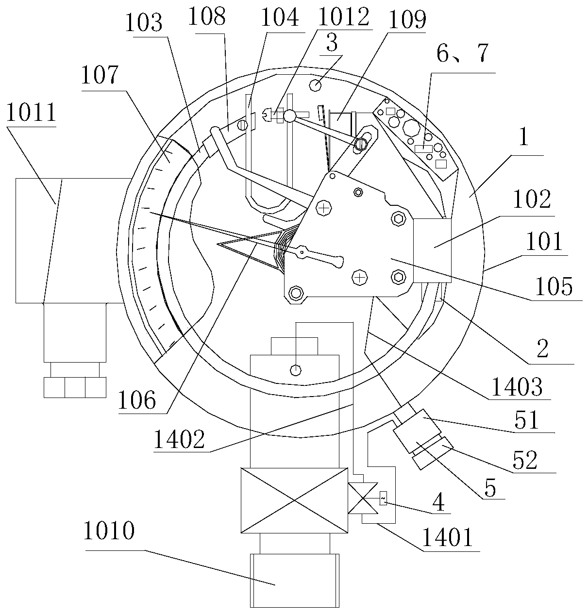
[0077] figure 1 It is a schematic structural diagram of a gas density relay for self-testing contact resistance of a contact point used for high and medium voltage electrical equipment in Example 1 of the present application. Such as figure 1 As shown, the gas density relay 1 includes: a housing 101, and a base 102, an end seat 108, a pressure detector 103, a temperature compensating element 104, several signal generators 109, and a core 105 arranged in the housing 101 , Pointer 106, Dial 107 and Equipment Connection Joint 1010. One end of the pressure detector 103 is fixed on the base 102 and communicated with it, and the other end of the pressure detector 103 is connected to one end of the temperature compensation element 104 through the end seat 108, the The other end of the temperature compensating element 104 is provided with a crossbeam, and the crossbeam is provided with an adjusting member that pushes the signal generator 109 to make the contacts of the signal genera...

Embodiment 2

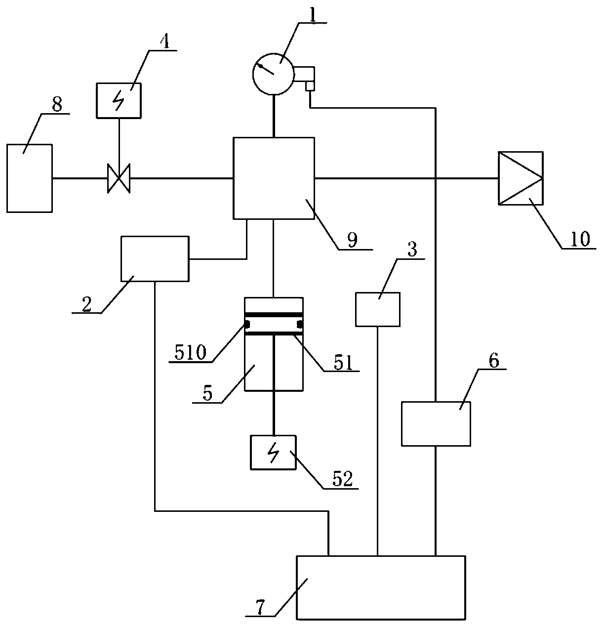
[0109] Such as Figure 4 As shown, the gas density monitoring device for self-test contact contact resistance provided by Embodiment 2 of the present invention includes: a gas density relay 1 (the gas density relay 1 mainly also includes: a housing, and a base, a pressure Detector, temperature compensation element, movement, pointer, dial, end seat, several signal generators and electrical equipment connection joints), pressure sensor 2, temperature sensor 3, valve 4, pressure adjustment mechanism 5, online calibration contact signal Sampling unit 6 and intelligent processor 7.

[0110] The air inlet of the valve 4 is sealed and connected to the electrical equipment through the electrical equipment connecting joint 1010 , and the air outlet of the valve 4 communicates with the base of the gas density relay 1 and the pressure detector. The pressure sensor 2, the temperature sensor 3, the online verification contact signal sampling unit 6, and the intelligent processor 7 are ar...

Embodiment 3

[0118] Such as Figure 5 As shown, the gas density monitoring device for self-test contact contact resistance provided by Embodiment 3 of the present invention includes: gas density relay 1, pressure sensor 2, temperature sensor 3, valve 4, pressure adjustment mechanism 5, online calibration contact signal sampling Unit 6, intelligent processor 7. The air inlet of the valve 4 is sealed and connected to the electrical equipment through the electrical equipment connection joint, and the air outlet of the valve 4 communicates with the base of the gas density relay 1 , the pressure sensor 2 and the pressure regulating mechanism 5 . The pressure sensor 2 , temperature sensor 3 , valve 4 and pressure regulating mechanism 5 are arranged on the rear side of the housing of the gas density relay 1 . The online verification contact signal sampling unit 6 and the intelligent processor 7 are arranged on the electrical equipment connection joint. The pressure sensor 2 communicates with th...


PUM


Abstract

The application provides a gas density relay for self-test junction contact resistance, and the relay comprises a housing, and a base, a pressure detector, a temperature compensation component, at least one signal generator, a signal adjustment mechanism and an equipment connection connector, which are all disposed in the housing. The gas density relay outputs junction signals through a number ofsignal generators and further comprises a contact resistance detecting unit and a junction signal isolation unit, wherein the contact resistance detecting unit is connected to the junction signals ordirectly connected to the signal generators. Under the action of the junction signal isolation unit, the junction of the gas density relay is isolated from its control loop, and the contact resistancedetecting unit can detect the junction contact resistance of the gas density relay when the junction of the gas density relay acts and/or when an instruction to detect the junction contact resistanceis received.

Description

technical field [0001] The invention relates to the field of electric power technology, in particular to a gas density relay and a monitoring system for self-testing contact resistance of high-voltage electrical equipment. Background technique [0002] At present, SF6 (sulfur hexafluoride) electrical equipment has been widely used in the power sector and industrial and mining enterprises, which has promoted the rapid development of the power industry. In recent years, with the rapid economic development, the capacity of my country's power system has expanded rapidly, and the amount of SF6 electrical equipment has increased. The role of SF6 gas in high-voltage electrical equipment is arc extinguishing and insulation. If the density of SF6 gas in high-voltage electrical equipment decreases and the micro-water content exceeds the standard, it will seriously affect the safe operation of SF6 high-voltage electrical equipment: 1) The density of SF6 gas is reduced to a certain exte...

Claims


Application Information

Patent Timeline
Patent Type & Authority Applications(China)
IPC IPC(8): G01N9/26G01D21/02G05B19/042G01R31/327
CPCG01D21/02G01N9/26G01R31/3272G01R31/3274G01R31/3275G05B19/0423
Inventor 金海生廖海明常敏曾伟贺兵谭庆
Owner SHANGHAI ROYE ELECTRICAL CO LTD
Why Eureka
Try Eureka