Optical receiving device capable of controlling optical efficiency in subdivision field

A technology of optical reception and field of view optics, which is applied in the field of lidar marine detection, can solve the problems of affecting the stability of output amplification, high noise of the detector amplification circuit, and difficulty in the detection of various strong scattering media, so as to meet the requirements of fast and stable detection , fast response and high reliability

Active Publication Date: 2019-11-12
SHANGHAI INST OF OPTICS & FINE MECHANICS CHINESE ACAD OF SCI
View PDF7 Cites 8 Cited by
  • Summary
  • Abstract
  • Description
  • Claims
  • Application Information

AI Technical Summary

Problems solved by technology

This technology has been widely used in laser three-dimensional imaging and atmospheric detection lidar, but in strong scattering media, the rise time of the gain curve reaches hundreds of nanoseconds, such a high-speed gain change will introduce high noise to the detector amplifier circuit, Affects the amplification stability of the output
[0008] The optical sub-field of view technology can realize the expansion of the detection dynamic range of the lidar system, and ensure the integrity and stability of the two channel signals in terms of time and intensity. However, the optical sub-field of view has a fixed distribution ratio, which is difficult to achieve. It is suitable for the detection of a variety of strong scattering media with different scattering intensities. Therefore, for the lidar currently used in a variety of strong scattering media, the detection dynamic range is still a key issue that needs to be solved and optimized

Method used


Image

  • Optical receiving device capable of controlling optical efficiency in subdivision field
  • Optical receiving device capable of controlling optical efficiency in subdivision field

Examples


Embodiment Construction

[0029] The present invention will be further described below in conjunction with example and accompanying drawing, but should not limit protection scope of the present invention with this.

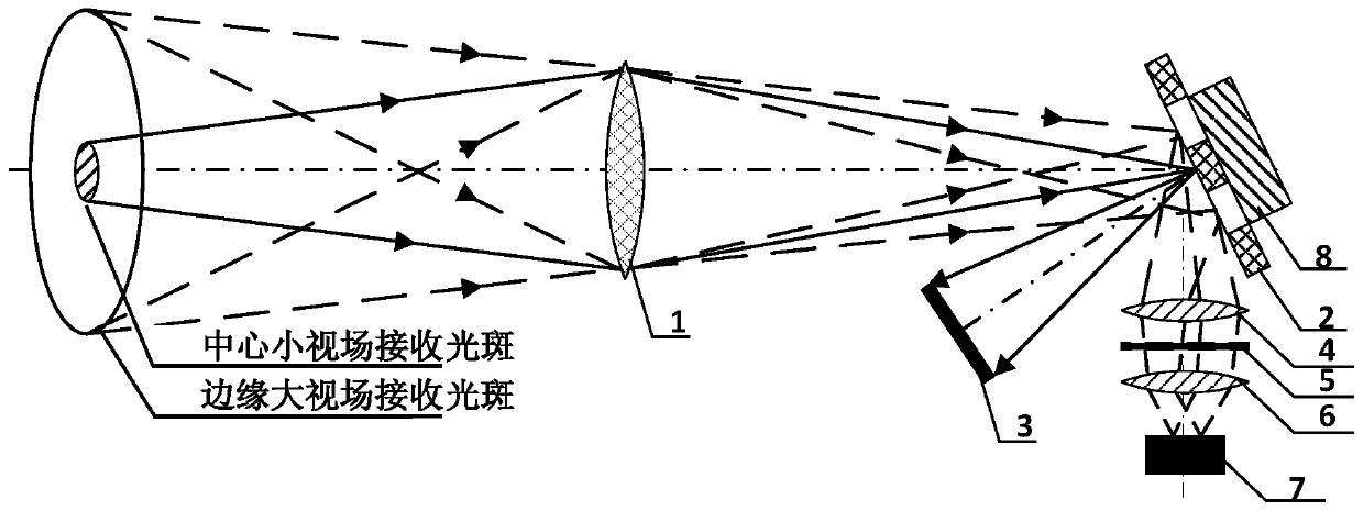
[0030] see first figure 1 , figure 1 It is the optical receiving device with controllable optical efficiency of subdivided field of view of the present invention. As can be seen from the figure, the optical receiving device with controllable optical efficiency of subdivided field of view of the present invention includes receiving main lens 1, DMD 2, light absorber 3, collimator Lens 4 , narrow band filter 5 , focusing lens 6 , detector 7 , DMD drive control module 8 .

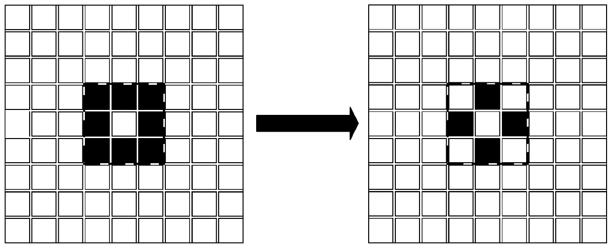
[0031] The receiving main lens 1 converges the echo of the laser light in the strong scattering medium onto the DMD, and the DMD drive control module is used to control the ratio of the number of micromirror units on the DMD corresponding to different viewing angles, The DMD2 has different optical efficiencies for receiv...


PUM


Abstract

An optical receiving device capable of controlling optical efficiency in a subdivision field. The optical receiving device comprises a receiving main lens, a DMD, a light absorbing body, a collimatinglens, a narrow band optical filter, a focusing lens, a detector, and a DMD driving control module. The optical receiving device can attenuate strong receiving light in a central small field and ensure weaker receiving light in a marginal large field to be received by the high sensitivity detector, thereby effectively overcoming the problem of signal saturation in he central field when laser radarmeasures a strong scattering medium. On the basis of ensuring the optical efficiency of the received light in the marginal large field, the optical receiving device achieves attenuation to the received light in the central small field, so as to effectively improve dynamic detection range of a laser radar system in strong scattering media such as water and fog.

Description

technical field [0001] The invention relates to the field of laser radar ocean detection, in particular to an optical receiving device with controllable optical efficiency of a subdivided field of view. Programmable control of field angle receiving light optical efficiency. On the basis of ensuring the optical efficiency of the received light in the large field of view at the edge, the attenuation of the received light in the small field of view in the center can be realized, which can effectively improve the detection dynamic range of the lidar system in strong scattering media such as water and fog. Background technique [0002] Lidar detects targets in strong scattering media such as water and fog. Due to the strong attenuation caused by strong scattering media, the distance attenuation of the target echo signal is much more serious than the attenuation in the conventional atmosphere. The detection dynamic range puts forward higher requirements. At present, the commonly...

Claims


Application Information

Patent Timeline
Patent Type & Authority Applications(China)
IPC IPC(8): G01S7/481
CPCG01S7/4816Y02A90/10
Inventor 陈勇强贺岩胡善江侯春鹤
Owner SHANGHAI INST OF OPTICS & FINE MECHANICS CHINESE ACAD OF SCI
Why Eureka
Try Eureka