Two-low-frequency two-high-frequency multiport base station antenna

A base station antenna, multi-port technology, applied in the field of two low and two high multi-port base station antennas, can solve the problem of poor radiation performance of the base station antenna, and achieve control of the windward surface area, size and weight reduction, good isolation index and radiation performance. Effect

Pending Publication Date: 2019-11-12
江苏泰科微通讯科技有限公司
View PDF0 Cites 5 Cited by
  • Summary
  • Abstract
  • Description
  • Claims
  • Application Information

AI Technical Summary

Problems solved by technology

[0005] In order to solve the problem that the existing base station antenna cannot support two low-frequency frequency bands and two high-frequency frequency bands at the same time, and cannot meet the technical requirements of both high and low frequency bands, and that the radiation performance of the base station antenna is poor, the present invention discloses a A multi-port base station antenna with two lows and two highs, in which a low-frequency radiation antenna array one, a low-frequency radiation antenna array two, a high-frequency radiation antenna array one and a high-frequency radiation Antenna array 2. The multi-port antenna can support two low frequencies and two high frequencies at the same time. At the same time, the antenna has good isolation index and radiation performance, and the performance has been greatly improved, effectively solving the above problems

Method used


Image

  • Two-low-frequency two-high-frequency multiport base station antenna
  • Two-low-frequency two-high-frequency multiport base station antenna
  • Two-low-frequency two-high-frequency multiport base station antenna

Examples


Embodiment Construction

[0031] The present invention is described in further detail now in conjunction with embodiment.

[0032] The units of length, width, height and distance in the present invention are mm.

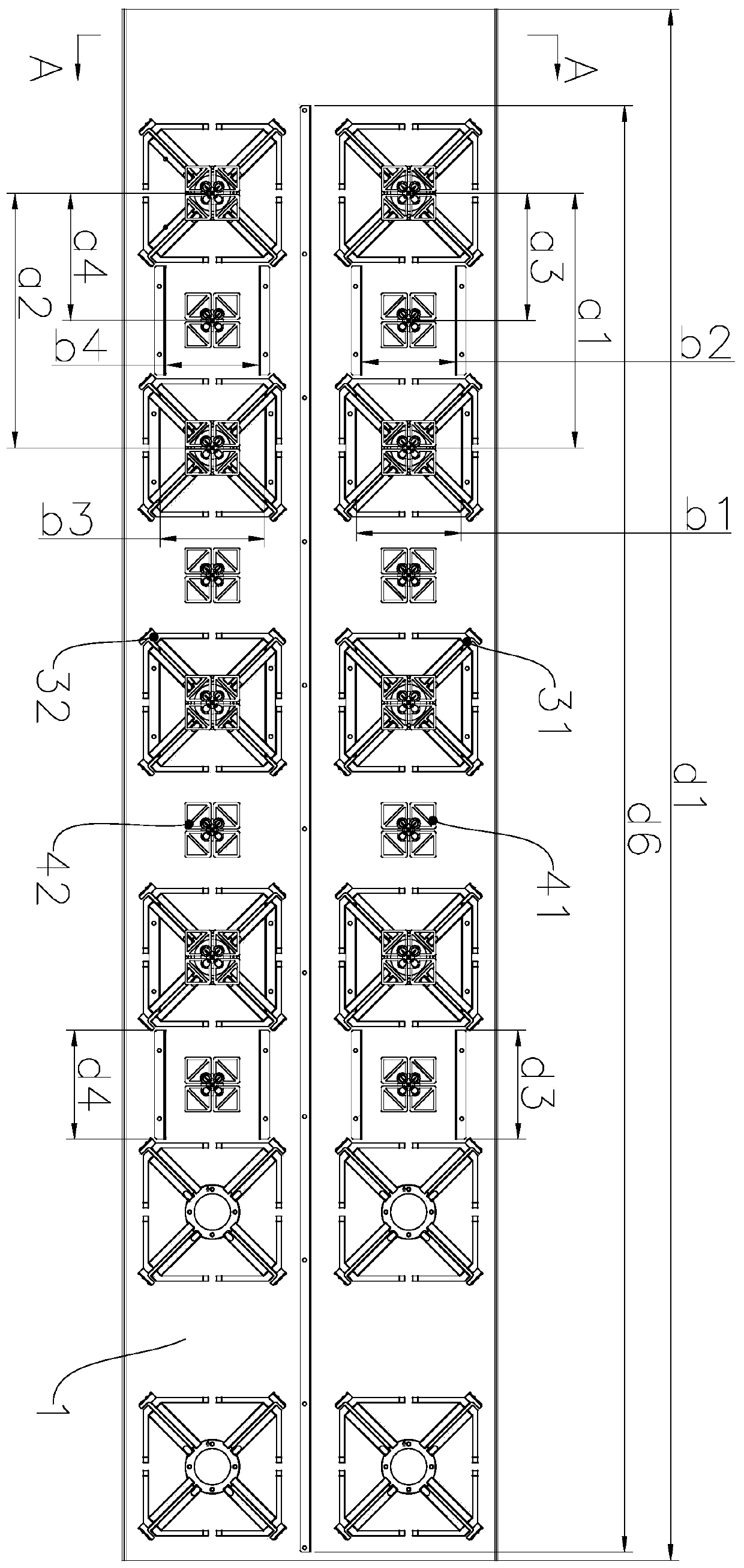
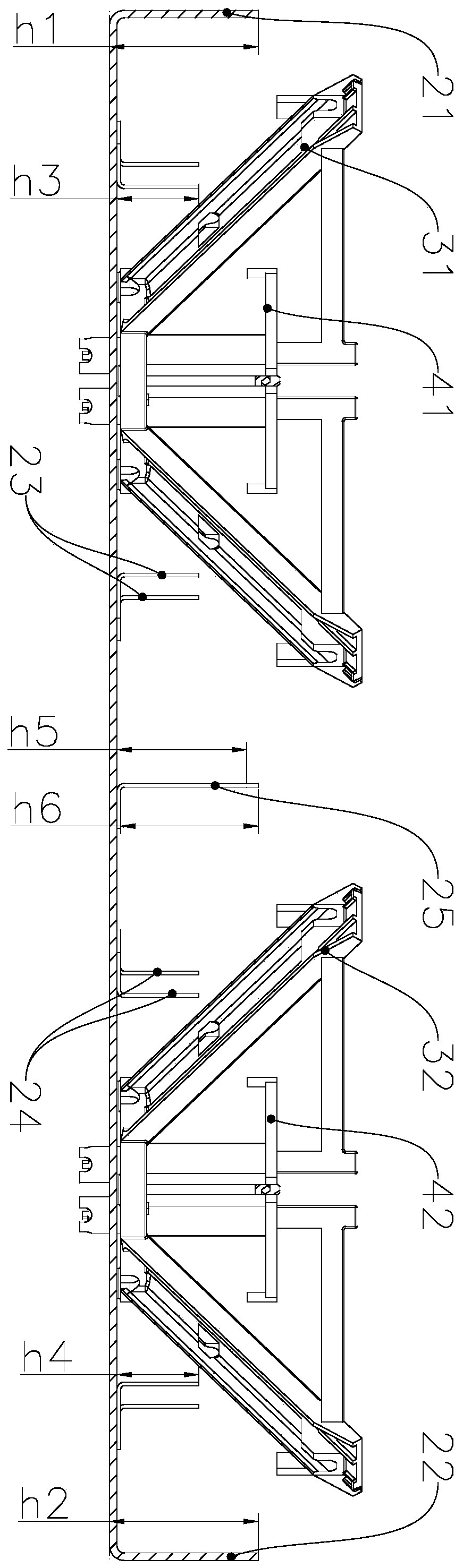
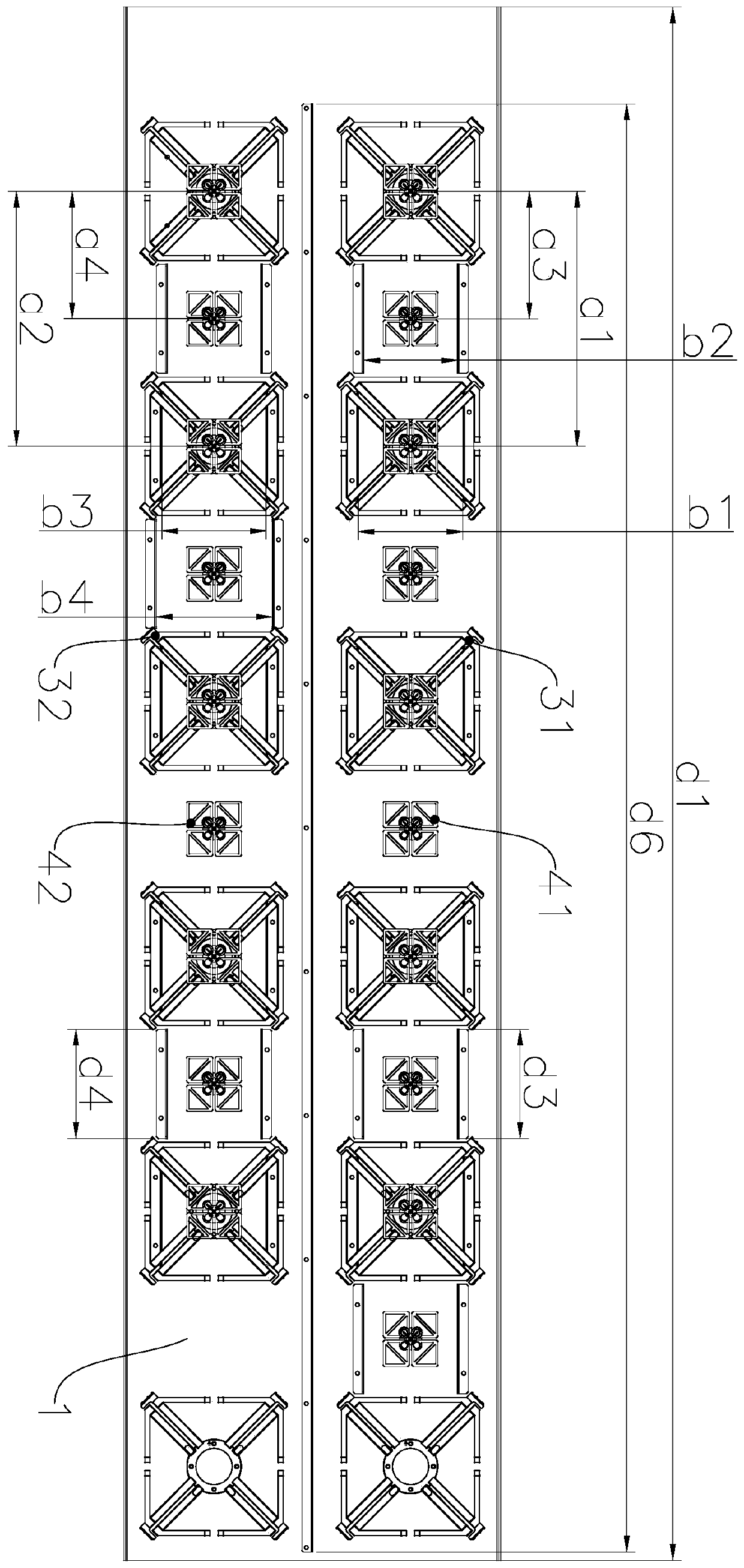
[0033] A two-low and two-high multi-port base station antenna, such as figure 1 and figure 2As shown, including base plate 1, reflector one 21 and reflector two 22 are respectively provided on both sides of base plate 1, and base plate 1 is provided with mutually parallel or overlapped low-frequency radiation antenna array one, low-frequency radiation antenna array two, high-frequency radiation Antenna array 1 and high-frequency radiation antenna array 2, low-frequency radiation antenna array 1 includes several low-frequency oscillators 1 31, low-frequency radiation antenna array 2 includes several low-frequency oscillators 2 32, high-frequency radiation antenna array 1 includes several high-frequency oscillators 1 41. The high-frequency radiation antenna array two includes several high-fr...


PUM


Abstract

The invention belongs to the technical field of base station antennas, in particular to a two-low-frequency two-high-frequency multiport base station antenna. The antenna comprises a bottom plate, anda first reflecting plate and a second reflecting plate are arranged at the two sides of the bottom plate correspondingly. A first low-frequency radiation antenna array, a second low-frequency radiation antenna array, a first high-frequency radiation antenna array and a second high-frequency radiation antenna array, which are parallel to or overlapped with one another, are arranged on the bottom plate. The first low-frequency radiation antenna array comprises a plurality of first low-frequency oscillators. The second low-frequency radiation antenna array comprises a plurality of second low-frequency oscillators. The first high-frequency radiation antenna array comprises a plurality of first high-frequency oscillators, and the second high-frequency radiation antenna array comprises a plurality of second high-frequency oscillators, wherein the first low-frequency oscillators and the first high-frequency oscillators are arrayed into a straight line and distributed on the bottom plate at equal intervals, and some of the first high-frequency oscillators are embedded into the first low-frequency oscillators close to the first reflecting plate; and the second low-frequency oscillators andthe second high-frequency oscillators are arrayed into a straight line, are distributed on the bottom plate at equal intervals and are close to the second reflecting plate, and some of the second high-frequency oscillators are embedded into the second low-frequency oscillators.

Description

technical field [0001] The invention belongs to the technical field of base station antennas, and in particular relates to a two-low and two-high multi-port base station antenna. Background technique [0002] In recent years, with the increase of mobile communication network standards, in order to save site and antenna resources, reduce the difficulty of property coordination, and reduce investment costs, multi-frequency array antennas with co-site and co-location have become the first choice for network construction. Moreover, in existing wireless communication systems, MIMO (Multiple-Input Multiple-Output) antenna technology is an important key technology to improve the quality and efficiency of mobile communication. MIMO technology can make full use of space resources and realize Multi-transmission and multi-reception can greatly increase the system channel capacity, improve channel reliability, and reduce the bit error rate without increasing spectrum resources and anten...

Claims


Application Information

Patent Timeline
Patent Type & Authority Applications(China)
IPC IPC(8): H01Q21/30H01Q19/185H01Q21/08H01Q1/36
CPCH01Q1/36H01Q19/185H01Q21/08H01Q21/30
Inventor 丁勇孙晓波胡昂昂
Owner 江苏泰科微通讯科技有限公司
Why Eureka
Try Eureka