U-shaped beam shaping tool and corresponding shaping method

A U-shaped, tooling technology, applied in the field of vehicles, can solve the problems of long debugging and rectification period, complex mold structure, low production efficiency, etc., and achieve the effect of reducing debugging time and difficulty, simple tooling structure and high production efficiency

Inactive Publication Date: 2019-11-15
ANHUI JIANGHUAI AUTOMOBILE GRP CORP LTD
View PDF8 Cites 3 Cited by
  • Summary
  • Abstract
  • Description
  • Claims
  • Application Information

AI Technical Summary

Problems solved by technology

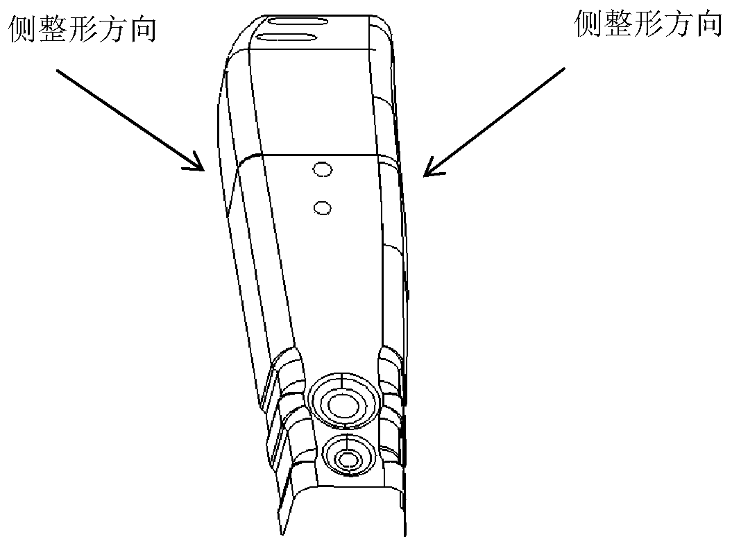
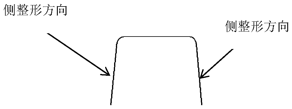
[0004] The main purpose of the present invention is to propose a U-shaped beam shaping tool and corresponding shaping method, aiming at solving the complex mold structure, high investment cost, and long debugging and rectification period caused by the use of traditional molds in the existing U-shaped beam shaping process. , the problem of low production efficiency

Method used


Image

  • U-shaped beam shaping tool and corresponding shaping method
  • U-shaped beam shaping tool and corresponding shaping method
  • U-shaped beam shaping tool and corresponding shaping method

Examples


Embodiment Construction

[0032] The following will clearly and completely describe the technical solutions in the embodiments of the present invention with reference to the accompanying drawings in the embodiments of the present invention. Obviously, the described embodiments are only part of the embodiments of the present invention, not all of them. Based on the embodiments of the present invention, all other embodiments obtained by persons of ordinary skill in the art without creative efforts fall within the protection scope of the present invention.

[0033] It should be noted that if there is a directional indication (such as up, down, left, right, front, back...) in the embodiment of the present invention, the directional indication is only used to explain the position in a certain posture (as shown in the accompanying drawing). If the specific posture changes, the directional indication will also change accordingly.

[0034] In addition, if there are descriptions involving "first", "second" and ...


PUM


Abstract

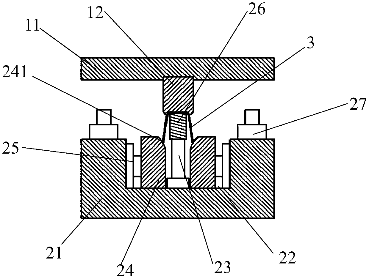
The invention discloses a U-shaped beam shaping tool and relates to the technical field of vehicles. The U-shaped beam shaping tool comprises an upper die body, and a lower die body matched with the upper die body. The upper die body comprises an upper die base. An upper die core is connected to the bottom of the upper die base. The lower die body comprises a lower die base. A groove opened upwards is formed in the upper end face of the lower die base. A jacking mechanism, lower die shaping cutter blocks and side pushing mechanisms are arranged in the groove. The jacking mechanism is installedat the bottom end of the groove. A carrier core is arranged on the top of the jacking mechanism. The lower die shaping cutter blocks are arranged on the left side and the right side of the jacking mechanism. The side pushing mechanisms are connected to the back ends of the lower die shaping cutter blocks. A height adjustable upsetting block is arranged on the upper end face, connected with the groove, of the lower die base. The invention further discloses a U-shaped beam shaping method. According to the tool and the method, the former side shaping or front shaping technology is changed into adriving extrusion technology, on the condition of ensuring the product quality, debugging time and difficulty can be shortened and reduced substantially, the adopted tool is simple in structure and low in investment cost, and parts of multiple specifications can be produced.

Description

technical field [0001] The invention relates to the technical field of vehicles, in particular to a U-shaped beam shaping process for a vehicle, in particular to a U-shaped beam shaping tool and a corresponding shaping method. Background technique [0002] U-shaped beam is a common part in the automobile industry and machinery industry. With the advancement of light weight, the strength level of the material of the part is continuously improved, and the rebound of the U-shaped beam is also increasing. [0003] For the parts of U-shaped beams, most of them adopt the method of mold side shaping, but the mold structure of this scheme is complicated, the investment cost is high, the debugging and rectification period is long, and the production efficiency is low; the specific performance is as follows: (1) The current process The scheme must use a cam (CAM) assembly, and the cost of the cam assembly is high and takes up space; the use of this process scheme will inevitably cause...

Claims


Application Information

Patent Timeline
Patent Type & Authority Applications(China)
IPC IPC(8): B21D3/10B21D37/10B21D45/04B21D53/88B21D47/01
CPCB21D3/10B21D37/10B21D45/04B21D47/01B21D53/88
Inventor 刘迪祥王双枝王淑俊张海洲张稳定方玲黄顶社黄永生
Owner ANHUI JIANGHUAI AUTOMOBILE GRP CORP LTD
Why Eureka
Try Eureka