Equipment for automatically welding collecting pipe bracket

An automatic welding and collecting tube technology, applied in welding equipment, auxiliary welding equipment, welding/cutting auxiliary equipment, etc. Effect

Pending Publication Date: 2019-11-15
杭州中久自控系统有限公司
View PDF0 Cites 4 Cited by
  • Summary
  • Abstract
  • Description
  • Claims
  • Application Information

AI Technical Summary

Problems solved by technology

[0003] The purpose of the present invention is to overcome the deficiencies of the prior art, and provides an automatic welding equipment for the header bracket to solve the technical problems of low welding consistency in the prior art

Method used


Image

  • Equipment for automatically welding collecting pipe bracket
  • Equipment for automatically welding collecting pipe bracket
  • Equipment for automatically welding collecting pipe bracket

Examples


Embodiment 1

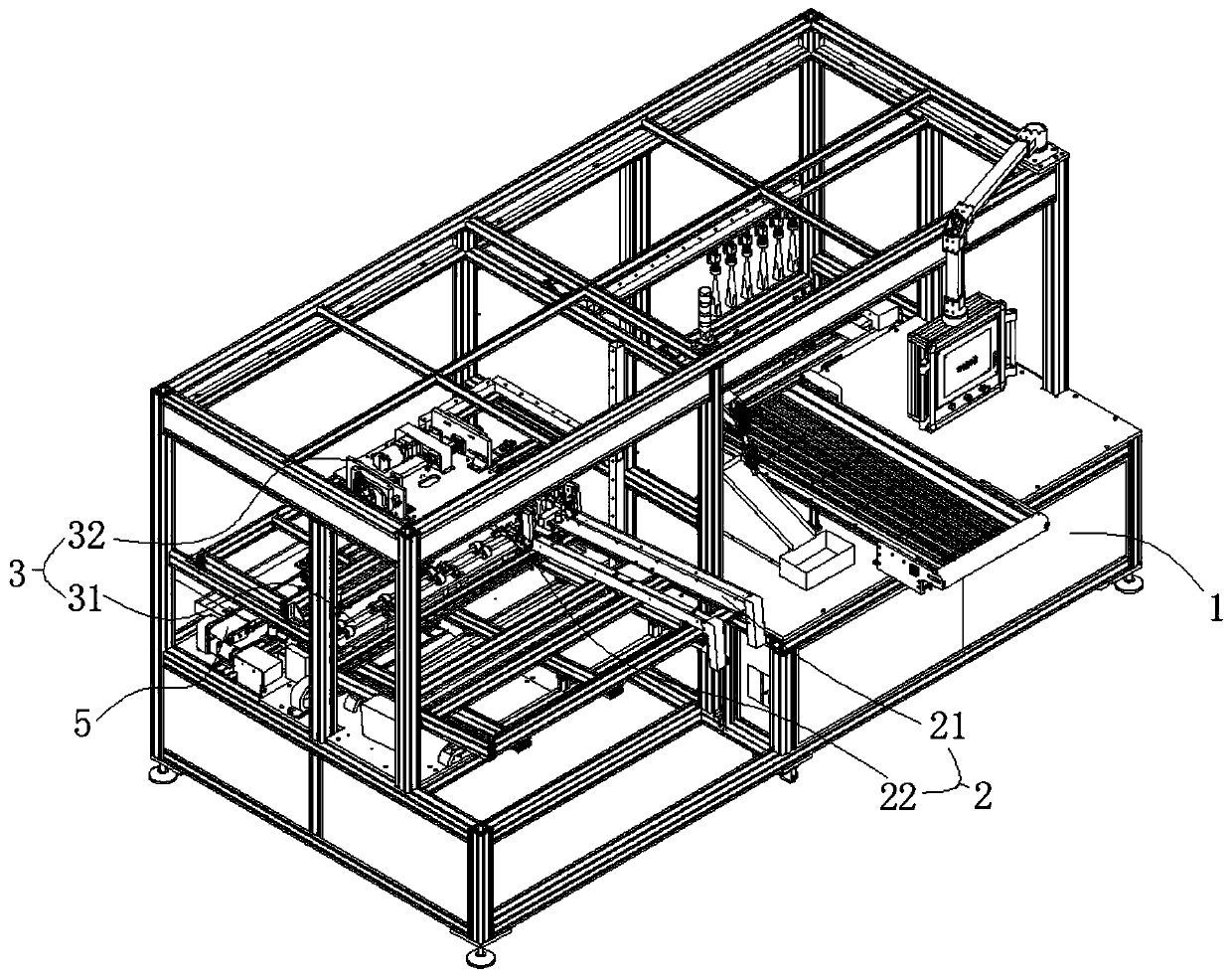
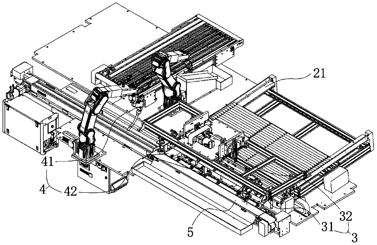
[0058] Embodiment 1 discloses header bracket automatic welding equipment, with reference to figure 1 and figure 2 , including a bracket body 1, the bracket body 1 is provided with a feeding device 2, a positioning device 3 and a welding device 4;

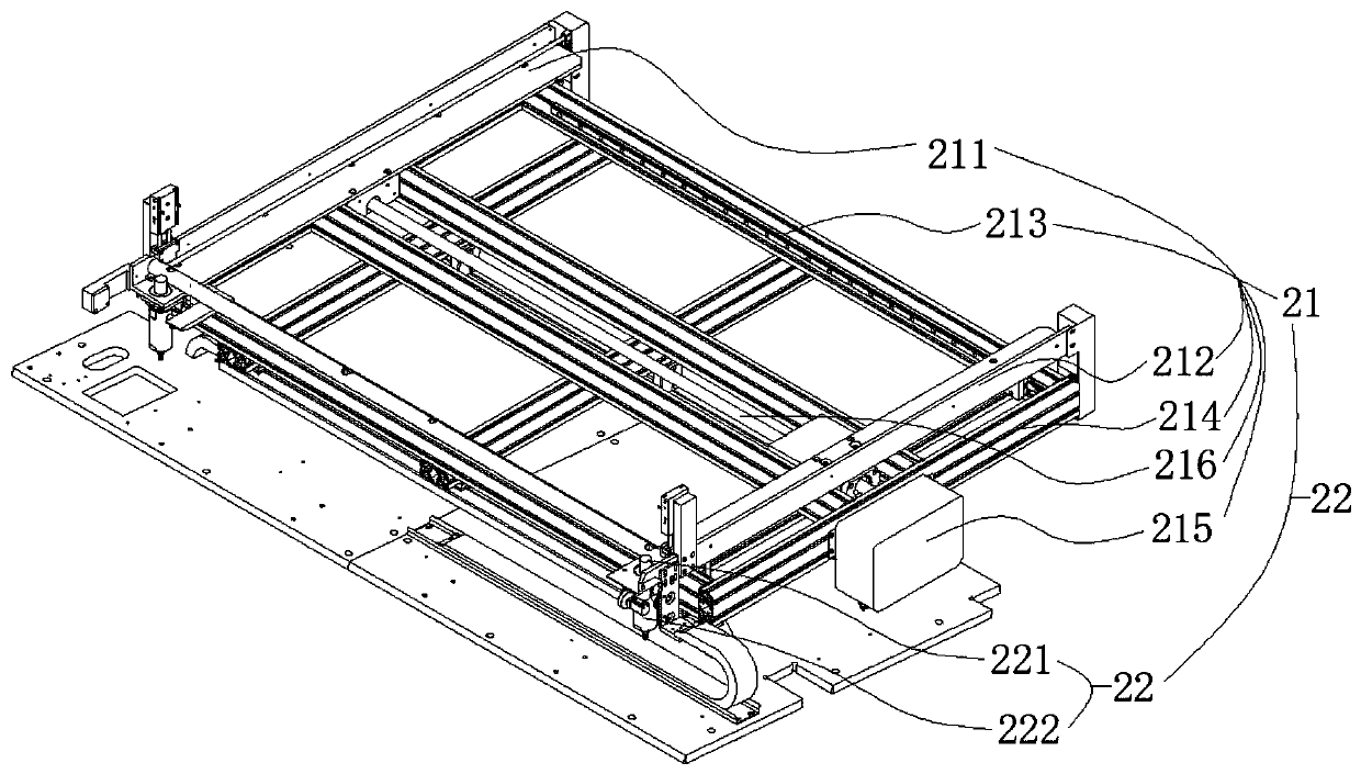
[0059] The feeding device 2 includes a support base 21 and a blocking assembly 22;

[0060] The support seat 21 forms a receiving surface for placing the workpiece to be processed, and the receiving surface is inclined so that the processed workpiece located on the receiving surface can move to the positioning device 3 under the action of gravity;

[0061] The inclination angle formed by the receiving surface and the horizontal angle can be set to 5 degrees, so that the header bracket can slide on the receiving surface to the positioning device 3 relatively quickly under the action of gravity only.

[0062] The stopper assembly 22 is arranged on the receiving surface near the end of the positioning device 3, referring to image ...


PUM


Abstract

The invention discloses equipment for automatically welding a collecting pipe bracket. The equipment comprises a bracket body, wherein a feeding device, a positioning device and a welding device are arranged on the bracket body; the feeding device comprises a supporting seat which forms an inclined bearing surface to enable the collecting pipe bracket to move to the positioning device under the action of gravity; the positioning device comprises a positioning assembly and a conveying assembly; the positioning assembly is use for determining the welding position of the collecting pipe bracket;the conveying assembly is used for transferring the positioned collecting pipe bracket to the welding device; the welding device comprises a welding execution assembly and a welding transmission assembly which are fixed on the bracket body; the welding transmission assembly comprises a welding fixing part and a welding transmission part; the welding fixing part is used for clamping the collectingpipe bracket on the conveying assembly; and when the welding transmission part drives the collecting pipe bracket to move to the welding execution assembly, the welding execution assembly welds the collecting pipe bracket. The equipment for automatically welding the collecting pipe bracket solves the problems of the low consistency of the existing manual welding and the like, and has the advantages of good applicability, small welding positioning error, high welding efficiency and the like.

Description

technical field [0001] The invention relates to the technical field of collecting pipe support processing equipment, in particular to automatic welding equipment for collecting pipe support. Background technique [0002] The header brackets for existing heat exchangers are usually directly connected to the heat exchange flat tubes without any diversion measures. After entering the header brackets, the gas-liquid two-phase stratification phenomenon is obvious, resulting in uneven distribution of refrigerant entering the heat exchange flat tubes , The heat transfer performance of the heat exchanger is poor. In recent years, there has been a shunt technology of inserting shunt tubes into the header brackets to improve the heat transfer performance of the heat exchanger. This requires opening holes on the header brackets and welding sockets for inserting shunt tubes. The existing technology Usually, the nozzle socket is welded manually with the help of tooling, and the welding ...

Claims


Application Information

Patent Timeline
Patent Type & Authority Applications(China)
IPC IPC(8): B23K37/00B23K37/04
CPCB23K37/00B23K37/0426B23K2101/14
Inventor 叶维妙孙国东岳靖伟蒋庆
Owner 杭州中久自控系统有限公司
Why Eureka
Try Eureka