Flexible finger control method

A technology of flexible fingers and control methods, applied in manipulators, manufacturing tools, chucks, etc., can solve the problems of complex control methods, high prices, and increased user costs.

Active Publication Date: 2019-11-15
SUZHOU ROROBOT TECH CO LTD
View PDF14 Cites 0 Cited by
  • Summary
  • Abstract
  • Description
  • Claims
  • Application Information

AI Technical Summary

Problems solved by technology

The control method of this kind of control system is relatively complicated, it needs to switch back and forth between positive pressure and negative press

Method used


Image

  • Flexible finger control method
  • Flexible finger control method
  • Flexible finger control method

Examples


Embodiment 1

[0042] The pneumatic actuator in this embodiment is a pneumatic clamping mechanism, and the flexible finger 4 is installed on the execution end of the pneumatic clamping mechanism; Pressure, the pneumatic clamping mechanism drives the flexible finger 4 to move and cooperates with the positive pressure bending deformation of the flexible finger 4 to form a combined clamping force; when the clamping force needs to be released, the pneumatic clamping mechanism drives the flexible finger 4 to reset, and the flexible finger 4 releases pressure Reset to release the clamping force.

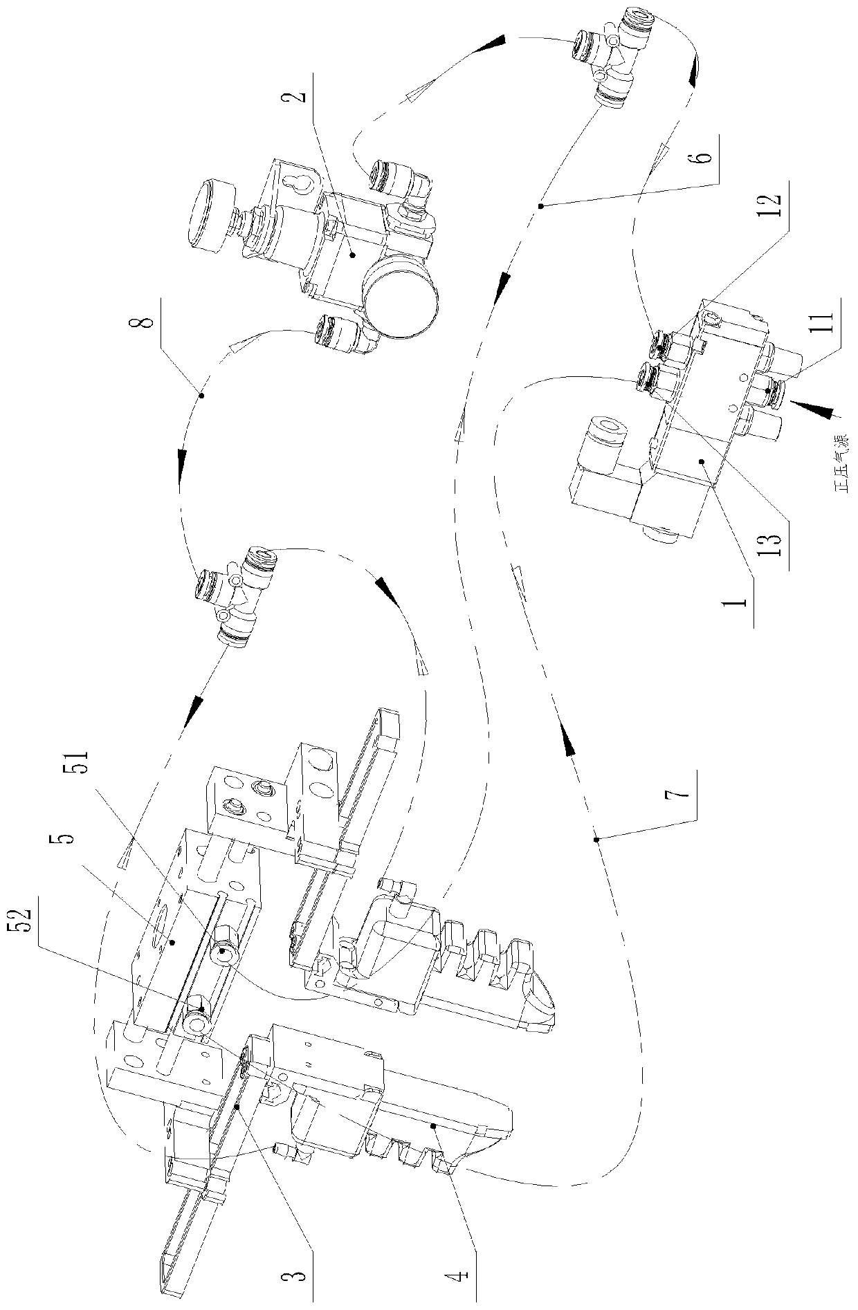
[0043] However, the pneumatic clamping mechanism in this embodiment adopts a linear translational pneumatic opening and closing mechanism 3 . Such as figure 1 As shown, the linear translation opening and closing mechanism 3 includes a guide plate 31, and the guide plate 31 is provided with a guide chute 32, and a finger mounting plate 33 is slidably installed in the guide chute 32, and the flexible fing...

Embodiment 2

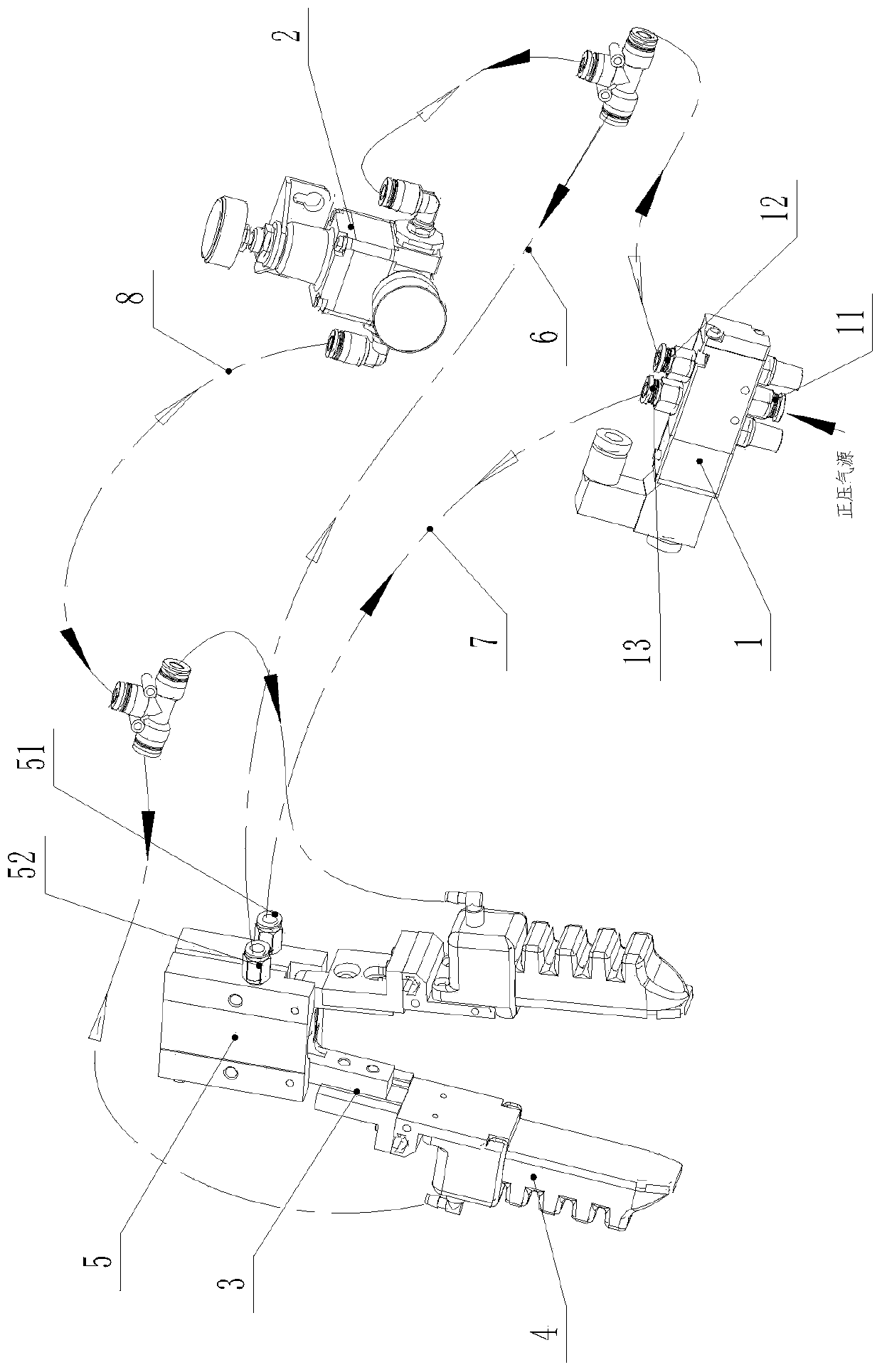
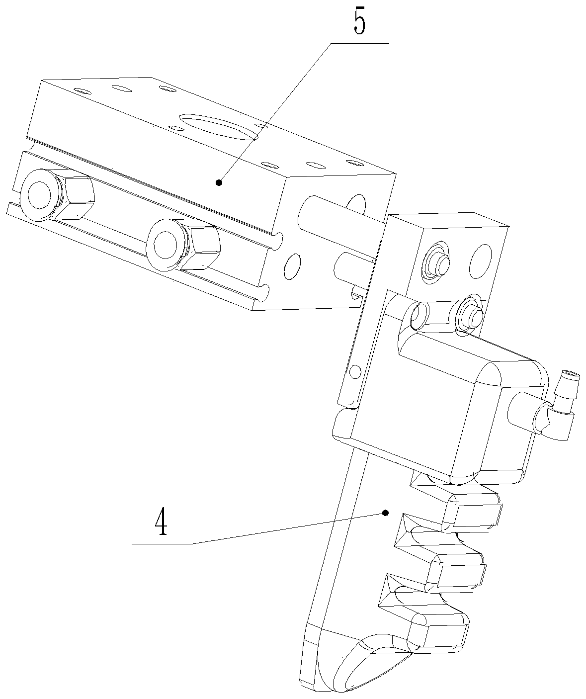
[0054] The structure of this embodiment is similar to that of Embodiment 1, except that the pneumatic actuator is a cylinder 5, and the flexible finger 4 is installed on the execution end of the cylinder 5; in this embodiment, the flexible finger 4 is directly installed on the cylinder 5 execution side, such as figure 2 As shown, the cylinder 5 is a Y-shaped jaw cylinder 5, and the Y-shaped clamping cylinder 5 can drive the deflection of the flexible finger 4, thereby completing the mobile drive of the flexible finger 4.

[0055] When it is necessary to provide clamping force, the positive pressure air supply system provides positive pressure on the flexible finger 4, and the cylinder 5 drives the flexible finger 4 to move and cooperate with the positive pressure bending deformation of the flexible finger 4 to form a combined clamping force; when it is necessary to release the clamping force , the cylinder 5 drives the flexible finger 4 to reset, and the flexible finger 4 rel...

Embodiment 3

[0059] Such as Figure 4 As shown, the structure of this embodiment is basically the same as that of Embodiment 1, except that the installation of the flexible fingers 4 is changed, and the bottom plate of the flexible fingers 4 faces outward, so that the clamping force can be provided from the inside out. When providing the clamping force, the action of the cylinder 5 is from the inside to the outside, thereby jointly providing the clamping force from the inside to the outside. Correspondingly, when resetting, both the flexible finger 4 and the cylinder 5 can be reversely reset.


PUM


Abstract

The invention discloses a flexible finger control method. According to the method, a pneumatic executing element and flexible fingers are provided; the pneumatic executing element and the flexible fingers are communicated with a positive pressure gas supply system through an executing element driving gas way and a finger driving gas way with a pressure regulating element respectively; when clamping force needs to be provided, the positive pressure gas supply system provides positive pressure to the pneumatic executing element and the flexible fingers to make the pneumatic executing element actto cooperate with the flexible fingers to be bent to form combined clamping force; and when the clamping force needs to be removed, the pneumatic executing element is restored, and the flexible fingers are decompressed and restored through self elasticity. According to the control method, opening and closing of an opening and closing mechanism are used for forming positive pressure bending matched with the flexible fingers to achieve clamping and loosing of an article, a vacuum generator and negative pressure bending action are abandoned, the control mode of the flexible fingers is greatly simplified, and cost is also reduced.

Description

technical field [0001] The invention relates to a flexible finger control method, and also relates to a flexible grasping device using the flexible finger control method. Background technique [0002] In the field of industrial automation, the grasping action at the end of the robotic arm is mainly completed by rigid mechanical grippers or vacuum suction cups. However, due to the difficulty in controlling the strength of rigid mechanical grippers, it is difficult to achieve non-destructive grasping of soft and fragile objects. It is difficult for vacuum suction cups to adapt to irregular objects with rough surfaces and holes during handling. This leads to limitations in both application scenarios. In response to the above problems, the applicant applied for a new type of flexible finger, the patent number is 201720979513.0, and expanded some flexible clamps for this new type of flexible finger, which can be used to flexibly clamp objects, thus solving the current problem ...

Claims


Application Information

Patent Timeline
IPC IPC(8): B25J15/02B25J15/08
CPCB25J15/0206B25J15/0253B25J15/08
Inventor 张帆沈科张笛沈津竹
Owner SUZHOU ROROBOT TECH CO LTD
Why Eureka
Try Eureka