Pumping unit wellhead oil gathering system and using method
A technology for pumping wells and pumping units, which is used in earth-moving drilling, wellbore/well components, and production of fluids, etc., can solve problems such as low efficiency of drilling wells, cumbersome procedures, and polished rods of oil wells, to prevent liquid The effect of backflow, enhanced oil recovery, and reduced pressure holding work
- Summary
- Abstract
- Description
- Claims
- Application Information
AI Technical Summary
Problems solved by technology
Method used
Image

Examples
Embodiment 1
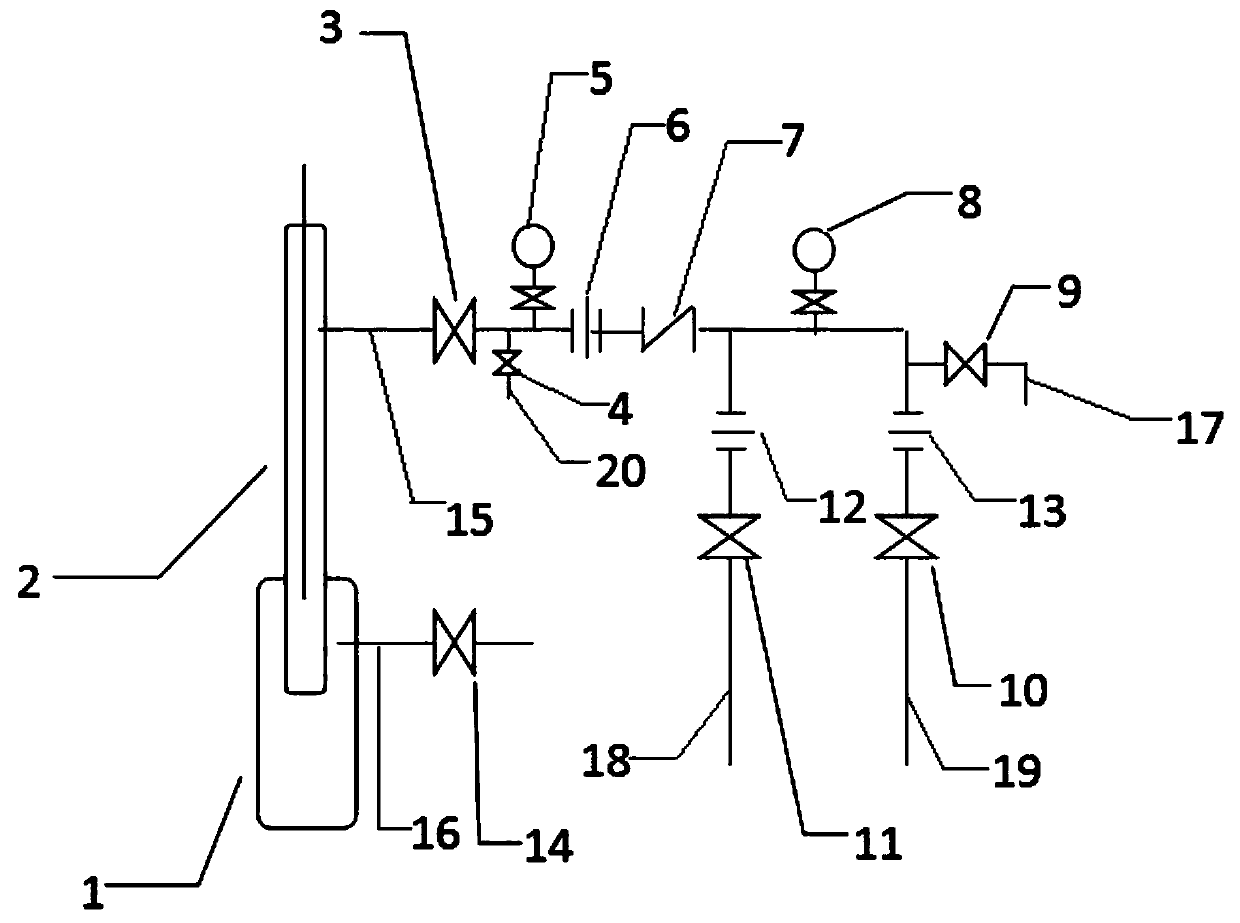
[0040] refer to figure 1 , a pumping unit wellhead oil gathering system, comprising
[0041] Pumping unit wellhead 2;
[0042] The wellhead casing 1 of the pumping unit, the wellhead casing 1 of the pumping unit is arranged at the bottom of the wellhead 2 of the pumping unit;
[0043] Natural gas exhaust pipeline 16, the natural gas exhaust pipeline 16 communicates with the wellhead casing 1 of the pumping unit;
[0044] The oil discharge pipeline 15 is connected with the wellhead 2 of the pumping unit, and the oil discharge pipeline 15 is also connected with the production gate 3, and the oil discharge pipeline in the direction of the outlet of the production gate 3 is connected with a single-flow check through the first valve 6. The valve 7 and the oil discharge pipeline in the outlet direction of the single-flow check valve 7 are also connected in parallel with an oil discharge pipeline and a vent pipeline 17;
[0045] A sampling pipeline 20, the sampling pipeline 20 is ...
Embodiment 2
[0050] Compared with Embodiment 1, the difference of this embodiment is that the described oil outlet pipeline includes a single volume oil discharge pipeline 18 and a mixed oil discharge pipeline 19, and the single volume oil discharge pipeline 18 and the mixed oil discharge pipeline 19 respectively pass through The second valve 12 and the third valve 13 are connected to the oil discharge line 15 in the outlet direction of the single-flow check valve 7, and the second pressure gauge 8 is connected between the single volume oil discharge line 18 and the mixed oil discharge line 19 on the drain line 15 between them.
[0051] Preferably, the single-quantity oil discharge pipeline 18 and the mixed oil discharge pipeline 19 are respectively connected to both sides of the second pressure gauge 8, and the single-quantity oil discharge pipeline 18 is connected between the single-flow check valve 7 and the second pressure gauge 8 On the oil drain line 15 between, the vent line 17 is c...
Embodiment 3
[0055] Compared with Embodiment 2, the difference of this embodiment is that: the inner diameter of the back pressure single volume valve 11 and the back pressure mixing valve 10 is DN50mm gate, and the inner diameter of the vent gate 9 is DN15mm gate.
[0056] In actual use: the inner diameter of the back pressure single volume valve 11 and the back pressure mixing valve 10 is a DN50mm gate, so that the calibers of the single volume oil discharge pipeline 18 and the mixed oil discharge pipeline 19 match in actual use, which is the airtightness of the entire pipeline Better, can not leak oil, and the internal diameter of venting gate 9 is DN15mm gate, makes in actual use match with the caliber of venting pipeline 17, makes pipeline airtightness good.
PUM
 Abstract
Description
Claims
Application Information
 - R&D
- Intellectual Property
- Life Sciences
- Materials
- Tech Scout
- Unparalleled Data Quality
- Higher Quality Content
- 60% Fewer Hallucinations
Browse by: Latest US Patents, China's latest patents, Technical Efficacy Thesaurus, Application Domain, Technology Topic, Popular Technical Reports.
© 2025 PatSnap. All rights reserved.Legal|Privacy policy|Modern Slavery Act Transparency Statement|Sitemap|About US| Contact US: help@patsnap.com