Optical field spin angle momentum measuring device and method

A measurement device and angular momentum technology, applied in the field of optical measurement, can solve the problems of complex measurement and calculation process, high difficulty of experiment, high difficulty of experiment, and only the momentum and angular momentum of several specific directions can be obtained, so as to improve calculation Efficiency, simplicity of extraction method, avoidance of measuring and calculating the effect of the process

Active Publication Date: 2019-11-15
深圳市深光谷科技有限公司
View PDF4 Cites 2 Cited by
  • Summary
  • Abstract
  • Description
  • Claims
  • Application Information

AI Technical Summary

Problems solved by technology

At present, there are mainly the following methods for measuring the spin angular momentum of the light field: 1. Using the reconstruction algorithm of meter scattering nano-interference, measuring the interference signals of the scattered light of the nanosphere particles and the incident light at different angles to obtain the angular spectrum distribution , and then reconstruct and calculate the magnitude and phase of the light field, and finally calculate the spatial distribution of its spin angular momentum. This method can obtain complete light field information, but requires complex measurement and calculation processes; 2. A The method of directly measuring the dynamic characteristics of the light

Method used


Image

  • Optical field spin angle momentum measuring device and method
  • Optical field spin angle momentum measuring device and method
  • Optical field spin angle momentum measuring device and method

Examples


Embodiment Construction

[0048] The following will clearly and completely describe the technical solutions in the embodiments of the present invention with reference to the accompanying drawings in the embodiments of the present invention. Obviously, the described embodiments are only some, not all, embodiments of the present invention. Based on the embodiments of the present invention, all other embodiments obtained by persons of ordinary skill in the art without creative efforts fall within the protection scope of the present invention.

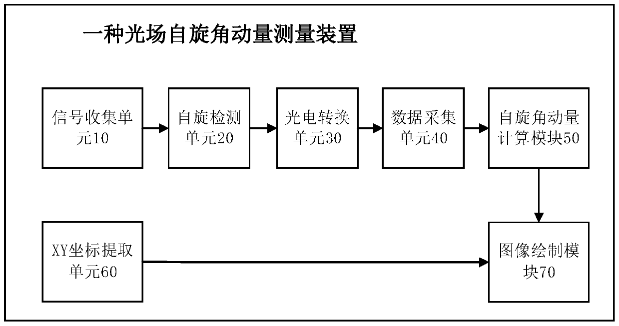
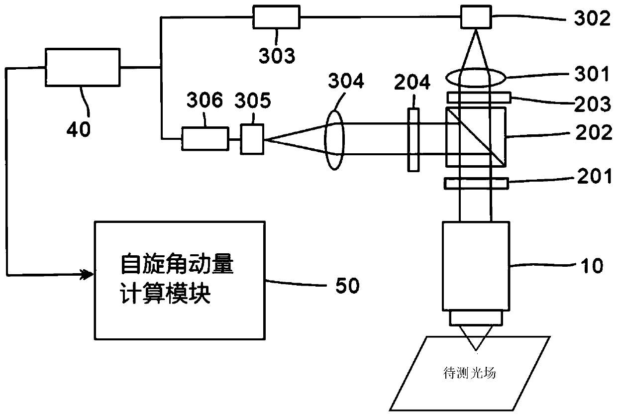
[0049] Such as figure 1 with figure 2 As shown, in one embodiment, a kind of optical field spin angular momentum measuring device is provided, comprising:

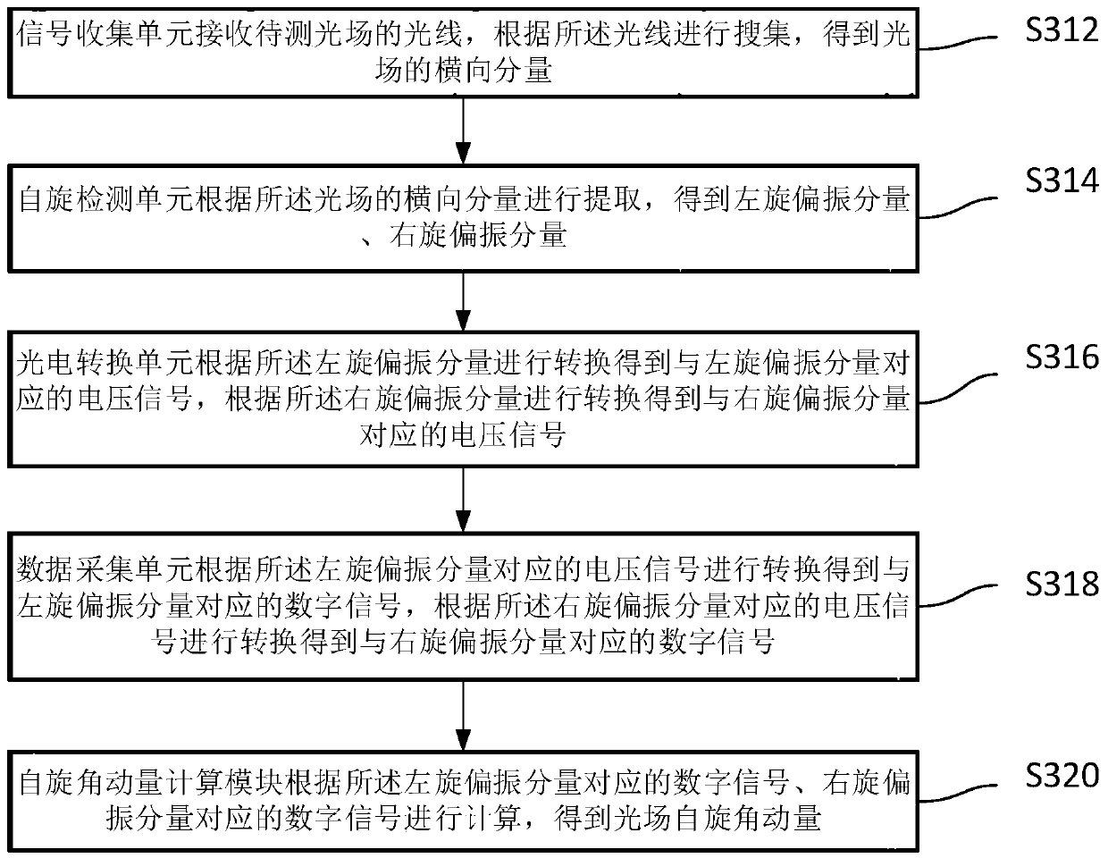
[0050] The signal collection unit 10 is configured to receive the light of the light field to be measured, collect according to the light, and obtain the transverse component of the light field;

[0051] The spin detection unit 20 is configured to extract according to the transverse component of the light fi...


PUM


Abstract

The invention relates to the technical field of optical measurement, in particular to an optical field spin angle momentum measuring device and method. The optical field spin angle momentum measuringdevice is used for collecting and obtaining a transverse component of a light field through a signal collecting unit; a spin detection unit is used for obtaining a left-handed polarization component and a right-handed polarization component through extraction; a photoelectric conversion unit is used for obtaining a voltage signal corresponding to the left-handed polarization component and a voltage signal corresponding to the right-handed polarization component through conversion; a data acquisition unit obtains a digital signal corresponding to the left-handed polarization component and a digital signal corresponding to the right-handed polarization component through conversion; and a spin angle momentum calculation module carries out calculation based on the digital signal correspondingto the left-handed polarization component and the digital signal corresponding to the right-handed polarization component to obtain the spin angle momentum of the light field. The extraction method issimple, complex measurement and calculation processes are avoided, and the calculation efficiency of the spin angle momentum of the light field is improved.

Description

technical field [0001] The invention relates to the technical field of optical measurement, in particular to an optical field spin angular momentum measurement device and method. Background technique [0002] Angular momentum plays an important role in the interaction between light and matter, and it can generally be divided into spin angular momentum and orbital angular momentum. The spin angular momentum depends on the polarization state of the light field, for example, left-handed circularly polarized light and right-handed circularly polarized light have different spin angular momentum; the orbital angular momentum is related to the specific spatial phase distribution of the light field, such as a vortex with a helical phase factor Optical field. Generally, the spin angular momentum and orbital angular momentum of light field in free space are considered as two independent degrees of freedom, but in non-homogeneous space light fields such as surface plasmon photonics an...

Claims


Application Information

Patent Timeline
IPC IPC(8): G01J1/42G01J4/04
CPCG01J1/42G01J4/04G01J4/02
Inventor 杜路平
Owner 深圳市深光谷科技有限公司
Why Eureka
Try Eureka