
Method and device for calculating directional diagram of beam pointing adjustable antenna

A technology of beam pointing and calculation method, applied in the directions of antenna radiation pattern, antenna, calculation, etc., can solve the problems such as difficulty in guiding the conduction or cut-off of slot units, high dependence on simulation software, inability to realize beam pointing and deflection, etc. Shape and switching, maneuverable effects

Pending Publication Date: 2019-11-15
SHENZHEN KUANG CHI HIGH END EQUIP TECH DEV LTD
View PDF0 Cites 2 Cited by
  • Summary
  • Abstract
  • Description
  • Claims
  • Application Information

AI Technical Summary

Problems solved by technology

[0007] Aiming at the problems in the related art that the beam pointing deflection cannot be realized, the dependence on the simulation software is large, and the principle of the phased array is difficult to guide the conduction or cut-off of the slot unit, the present invention proposes a calculation method for the direction diagram of the adjustable beam pointing antenna And the device can realize the weighted calculation of the beam pointing adjustable antenna pattern without relying on the simulation software; at the same time, the global optimization of each key parameter can be carried out to realize the rapid switching of the beam

Method used


Image

  • Method and device for calculating directional diagram of beam pointing adjustable antenna
  • Method and device for calculating directional diagram of beam pointing adjustable antenna
  • Method and device for calculating directional diagram of beam pointing adjustable antenna

Examples


Embodiment Construction

[0030] The following will clearly and completely describe the technical solutions in the embodiments of the present invention with reference to the accompanying drawings in the embodiments of the present invention. Obviously, the described embodiments are only some, not all, embodiments of the present invention. All other embodiments obtained by persons of ordinary skill in the art based on the embodiments of the present invention belong to the protection scope of the present invention.

[0031] According to an embodiment of the present invention, a method for calculating the pattern of an antenna with an adjustable beam direction is provided. The antenna with an adjustable beam direction is generally also called a leaky wave antenna, which includes a plurality of slots that generate leaky waves.

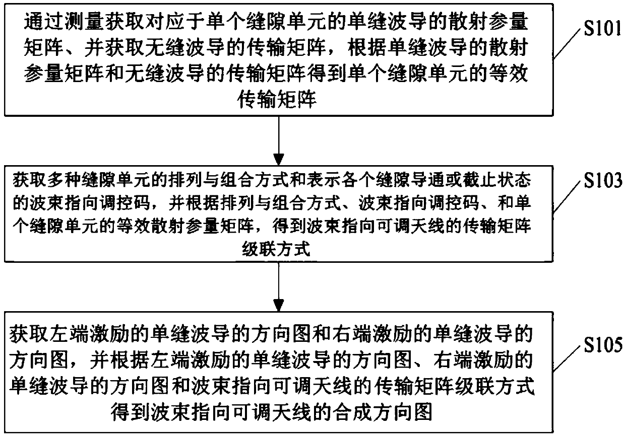
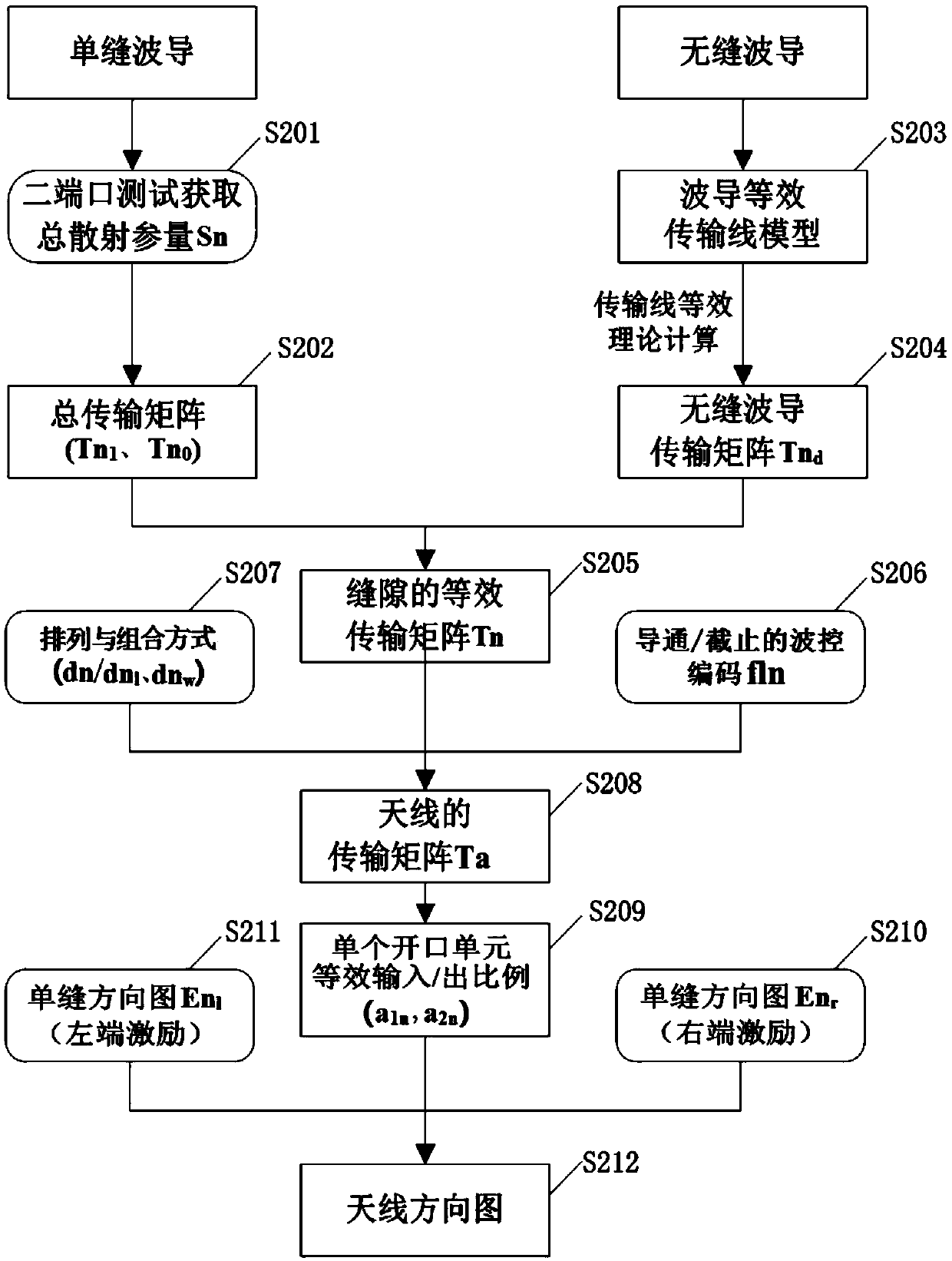
[0032] Such as figure 1 As shown, the method for calculating the pattern of the beam pointing adjustable antenna according to the embodiment of the present invention includes the fo...


PUM


Abstract

The invention discloses a method and a device for calculating a directional diagram of a beam pointing adjustable antenna. According to the design method, the scattering parameter of a single slot isobtained through direct measurement, the operability is high, and the calculation of a beam pointing adjustable antenna directional diagram without depending on simulation software is realized; meanwhile, weighted calculation of a beam pointing adjustable antenna directional diagram is realized; key information including slot unit forms, slot unit combinations, slot unit arrangement modes and thelike can be globally optimized, and optimization of slot unit selection, arrangement, combination, spacing and the like in antenna design is greatly saved so as to focus on the design of slot unit structure forms; besides, the wave control codes of the conduction and cut-off states corresponding to the slot units can be calculated according to the beam pointing deflection requirements so that guidance is provided for regulation of beam pointing and thus rapid forming and switching of the beams can be realized.

Description

technical field [0001] The present invention relates to the technical field of antennas, in particular to a method and device for calculating the direction diagram of an antenna with adjustable beam direction. Background technique [0002] The waveguide-based beam pointing adjustable antenna (leaky wave antenna) has the advantages of low cost, long life, low profile, full shielding to eliminate internal complex scattering, etc. The key factors in the design of adjustable beam pointing antennas include: slot unit, slot spacing, slot arrangement, slot turn-on and cut-off control, etc. Among them, in order to achieve precise control of specific beam pointing and low sidelobe control in the working frequency band, it is necessary to optimize the linkage of the above key factors. [0003] The design method of the beam-pointing adjustable antenna with traditional regular slots is relatively mature, and factors such as slot size and spacing are related to the antenna pattern forme...

Claims


Application Information

Patent Timeline
Patent Type & Authority Applications(China)
IPC IPC(8): G06F17/50
CPCH01Q21/29H01Q21/0043H04B7/0617G06F30/367H01Q13/085H01Q21/005H01Q21/0062G01R29/0871G01R29/10H01Q3/267
Inventor 刘若鹏赵治亚田华丁一
Owner SHENZHEN KUANG CHI HIGH END EQUIP TECH DEV LTD
Learn More