
Pluggable structure for L-type connectors of high-voltage cables of electric multiple units

A high-voltage cable and connector technology, applied in vehicle connectors, parts and connections of connecting devices, etc., can solve problems such as restricting the development of railway transportation, inconvenient product installation and post-maintenance, and products that cannot fully meet the pluggable function, etc. problem, to achieve the effect of convenient installation and simple structure

Pending Publication Date: 2019-11-15
CRRC QINGDAO SIFANG ROLLING STOCK RES INST +1
View PDF0 Cites 0 Cited by
  • Summary
  • Abstract
  • Description
  • Claims
  • Application Information

AI Technical Summary

Problems solved by technology

[0003] In recent years, with the continuous development of the EMU industry, the country has higher and higher performance requirements for 27.5kV L-type connectors for EMUs. At present, the products cannot fully meet the pluggable functions, and it is not convenient for product installation and later maintenance; currently 27.5 The performance of kV L-type connector seriously restricts the development of my country's railway transportation

Method used


Image

  • Pluggable structure for L-type connectors of high-voltage cables of electric multiple units

Examples


Embodiment 1

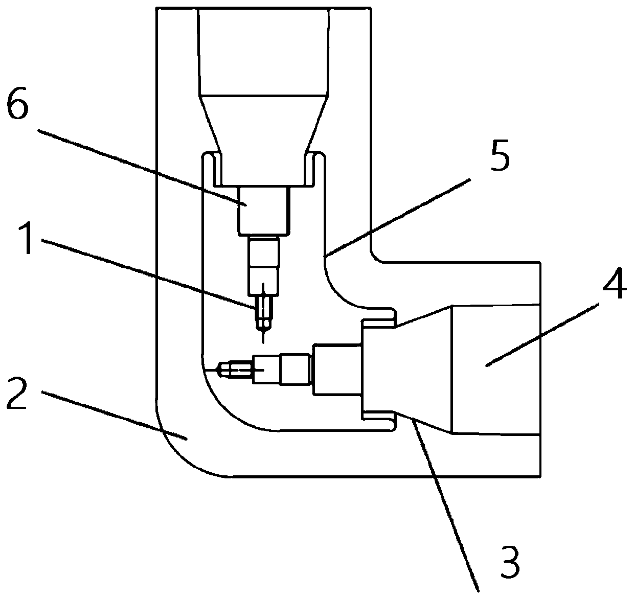
[0021] Such as figure 1 shown.

[0022] A pluggable structure for an L-shaped connector of a high-voltage cable of an EMU, comprising a pair of joint units arranged in an L shape; the pair of joint units are connected by an L-shaped connector, and the L-shaped connector includes a socket set The L-shaped central conductor 5 and the L-shaped insulating sleeve 2; the joint unit includes the contact head 1 and the stress cone 4 arranged in sequence; the two ends of the L-shaped central conductor 5 are provided with the contact head 1 and the stress cone 4 matching grooves;

[0023] The groove at the end of the L-shaped central conductor 5 is provided with a watch strap contact finger reed socket structure; one end of the contact head 1 is pluggably connected to the watch strap contact finger reed socket structure, and the other One end is connected to the cable 6; the stress cone 4 is a conical structure, and the top of the stress cone 4 is provided with an upper slope that mat...

Embodiment 2

[0026] As described in Embodiment 1, the pluggable structure for the L-shaped connector of the high-voltage cable of the EMU, further, the pluggable structure for the L-shaped connector of the high-voltage cable of the EMU also includes a protection unit, the The protection unit includes an L-shaped protective shell and an L-shaped cover plate matched with the L-shaped protective shell; both ends of the protective unit are open, and the joint unit is embedded in the opening at the end of the protective unit.

[0027] The material of the L-shaped central conductor 5 is aluminum alloy, and the surface layer is silver-plated; the material of the L-shaped insulating sleeve is epoxy resin; the material of the stress cone is EPDM rubber; the contact head is aluminum alloy, and the surface layer Silver plating treatment; Inorganic flame retardants and organic flame retardants are added to the components of the L-shaped insulating sleeve and the stress cone; the material of the protect...

Embodiment 3

[0029] As for the pluggable structure for the L-shaped connector of the high-voltage cable of the EMU described in Embodiment 1, further, the L-shaped insulating sleeve 2 is composed of a long tube and a short tube. One is short and the other is long for the insulation sleeve 2, which is convenient for distinguishing the installation units.


PUM


Abstract

The invention relates to a pluggable structure for L-type connectors of high-voltage cables of electric multiple units. The structure includes a pair of joint units arranged in an L shape. The joint units are connected by an L-shaped connecting piece, and the L-shaped connecting piece includes an L-shaped central conductor and an L-shaped insulating bushing which sleeves the L-shaped central conductor. Each joint unit includes a contact head and a stress cone which are arranged in sequence. The L-shaped central conductor is provided with grooves matched with the contact head and the stress cone at the two ends thereof. An L-shaped connecting head and the central conductor of the pluggable structure for L-type connectors of high-voltage cables of electric multiple units are arranged into aplugging structure. The structure is simple, pluggable and convenient to install.

Description

technical field [0001] The invention relates to a pluggable structure for an L-shaped connector of a high-voltage cable of an EMU, and belongs to the technical field of electric equipment for an EMU. Background technique [0002] With the continuous improvement of my country's transportation industry, China's EMUs have ushered in a golden age of construction and development. The 27.5kV L-shaped connector is an important part of the EMU traction power supply system, and its reliability directly affects the safe operation of the EMU. Among them, the L-shaped connector is installed on the top of the EMU train and connects the cables between the carriages. Its function is the same as that of the middle joint connecting two sections of cables in the power system, but the two ends of the cable connected by the middle joint in the power system are in the same straight line. On the EMU train, the two connecting cables are respectively located in the middle of the top of the train an...

Claims


Application Information

Patent Timeline
Patent Type & Authority Applications(China)
IPC IPC(8): H01R13/02H01R13/03H01R13/187H01R13/40H01R13/502H01R13/527H01R13/533H01R24/00H01R31/06
CPCH01R24/00H01R13/40H01R13/502H01R13/533H01R13/02H01R13/527H01R31/06H01R13/03H01R13/187H01R2201/26
Inventor 陈猛猛王祥王景兵程兆璐张存生杨黎明昝海斌董波沈兰晓
Owner CRRC QINGDAO SIFANG ROLLING STOCK RES INST
Learn More