Multi-part piston construction for an opposed-piston engine

An opposed-piston, multi-component technology, applied in engine components, machines/engines, pistons, etc., to solve problems such as increased piston construction cost and time, unreasonable mass production, and adverse effects on engine performance and efficiency

Inactive Publication Date: 2019-11-15
ACHATES POWERS INC
View PDF25 Cites 0 Cited by
  • Summary
  • Abstract
  • Description
  • Claims
  • Application Information

AI Technical Summary

Problems solved by technology

However, all other things being equal, a piston with a thicker skirt is heavier than a piston with a thinner skirt, which can adversely affect engine performance and efficiency
Additional machining of the forged skirt portion to reduce wall thickness adds cost and time to piston construction which may not be justified in mass production

Method used


Image

  • Multi-part piston construction for an opposed-piston engine
  • Multi-part piston construction for an opposed-piston engine
  • Multi-part piston construction for an opposed-piston engine

Examples


example 1

[0048] Material example 1: Assume that a three-part piston is designed for an opposed-piston engine where the end surfaces will experience peak cylinder pressures in excess of 200 bar. For durable high-strength construction, the crown member can be forged comprising 4140 steel, the skirt member can be forged comprising 4140 steel, and the outer member can be cut and machined from tubing comprising weldable wear-resistant steel. processing to obtain the desired characteristics. In some cases it may be desirable to forge the outer part from pieces comprising weldable wear resistant steel material.

example 2

[0049] Material example 2: Assume that a three-part piston is designed for an opposed-piston engine where the end surfaces will experience peak cylinder pressures less than or equal to 200 bar. For a durable construction of suitable strength, the crown member may be a forging comprising microalloyed steel, the skirt member may be a forging comprising microalloyed steel, and the outer member may be cut from tubing comprising weldable wear resistant steel and are machined to obtain the desired features. In some cases it may be desirable to forge the outer part from pieces comprising weldable wear resistant steel material.

[0050] manufacture: Image 6 Illustrated is a method 600 for manufacturing a piston for use in an opposed-piston engine as described herein. The method includes providing the piston with a crown component, as shown at 605 . As mentioned above, the crown part may be of a first material, while the rest of the piston is of a second material, or of two or ...


PUM


Abstract

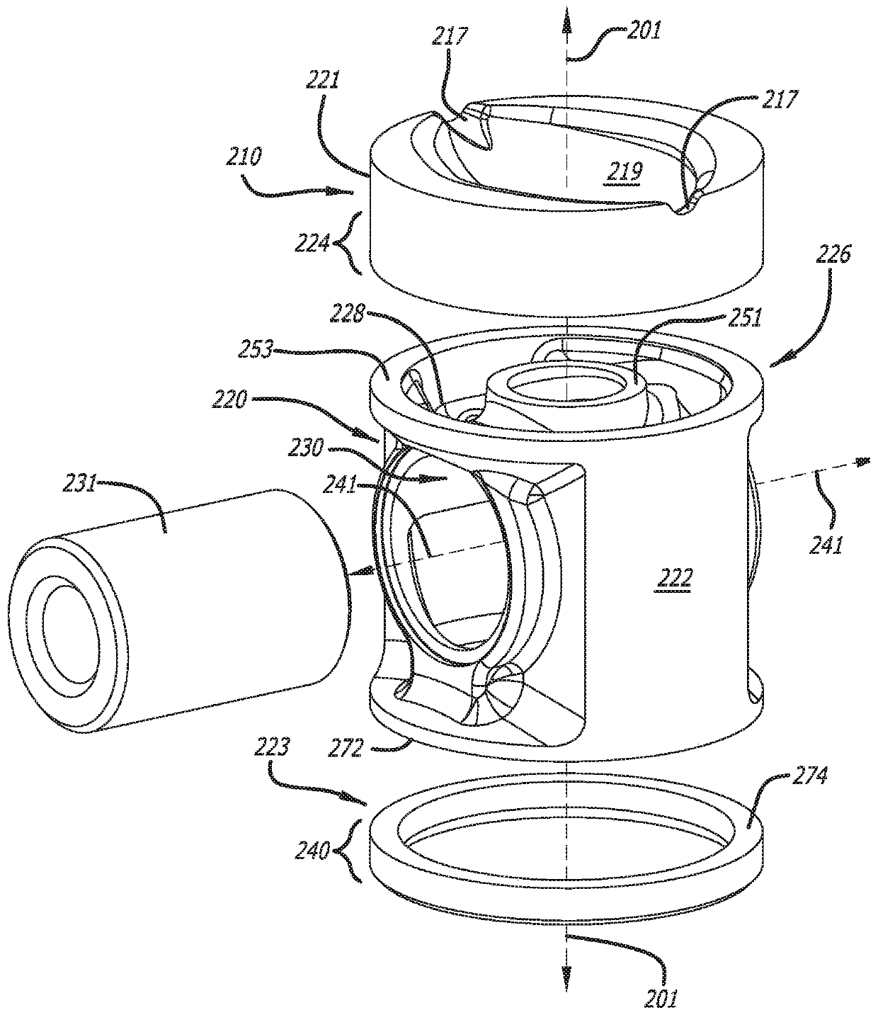
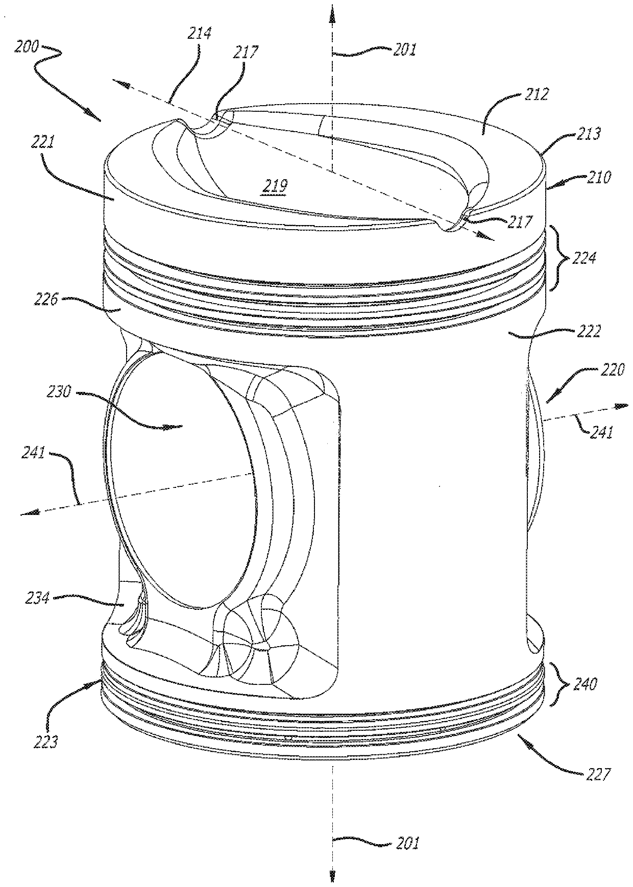
A piston for an internal combustion opposed-piston engine includes a crown part, a skirt part, and an outer part. The crown part includes a first ring belt region for supporting compression rings andan end surface shaped to form a combustion chamber with an end surface of an opposing piston. The skirt part includes a sidewall and a wristpin bore with a first opening and a second opening formed inthe sidewall. The outer part includes a second ring belt region for supporting oil control rings. The crown part is joined to an upper end of the sidewall with one or more welding seams. The outer part is joined to a lower end of the sidewall with a welding seam.

Description

[0001] related application [0002] This application contains subject matter related to that of the following patent application: U.S. Patent Application 13 / 136,955, "Piston Construction for Opposed Piston Engines," filed August 15, 2011, now U.S. Patent issued on October 20, 2015 No. 9,163,505; U.S. Patent Application 13 / 776,656 for "Oscillating Journal Bearings for Two-Stroke Cycle Engines," filed Feb. 25, 2013, now U.S. Patent No. 9,175,725 issued Nov. 3, 2015; Nov. 2013 U.S. Patent Application No. 14 / 075,926, "Lubrication Arrangement for Maintaining Wrist Pin Oil Pressure in Two-Stroke Cycle Opposed Piston Engines," filed May 8, now U.S. Patent No. 1, issued May 26, 2015 9,038,593; U.S. Patent Application No. 14 / 199,877, "Piston Cooling Arrangement Utilizing Lubricating Oil From Bearing Reservoirs in Opposed Piston Engines," filed March 6, 2014, now published October 18, 2016 U.S. Patent No. 9,470,136; U.S. Patent Application No. 14 / 596,855, "Piston Cooling of Opposed Pisto...

Claims


Application Information

Patent Timeline
IPC IPC(8): F02F3/00F02B75/28
CPCF02F3/0015F02F3/003F02B75/282F02F2003/0061F02F2200/00B23K26/28B23P15/10
Inventor R·G·麦肯齐
Owner ACHATES POWERS INC
Why Eureka
Try Eureka