Low loss galvanic isolation circuitry

A technology for galvanic isolation and isolation of circuits, applied in circuits, transmission systems, baseband systems, etc., and can solve problems such as increasing data delay, data rate limitation, and signal path attenuation.

Active Publication Date: 2019-11-15
TEXAS INSTR INC
View PDF8 Cites 0 Cited by
  • Summary
  • Abstract
  • Description
  • Claims
  • Application Information

AI Technical Summary

Problems solved by technology

However, capacitor-based isolation solutions typically involve absorbing signal energy and causing significant signal path attenuation due to bottom plate parasitic capacitance that shunts the signal energy to local ground
This results in poor power efficiency, and large parasitic capacitances can severely limit bandwidth, leading to data rate limitations and increased data latency
Additionally, these problems in capacitively coupled isolation devices can lead to poor common-mode performance

Method used


Image

  • Low loss galvanic isolation circuitry
  • Low loss galvanic isolation circuitry
  • Low loss galvanic isolation circuitry

Examples


Embodiment Construction

[0020] In the drawings, like reference numerals identify like elements throughout, and the various features are not necessarily drawn to scale. In this specification, the term "couple / coupled / couples" includes indirect or direct electrical or mechanical connections or combinations thereof. For example, if a first device is coupled to or with a second device, that connection may be through a direct electrical connection, or through an indirect electrical connection via one or more intervening devices and connections.

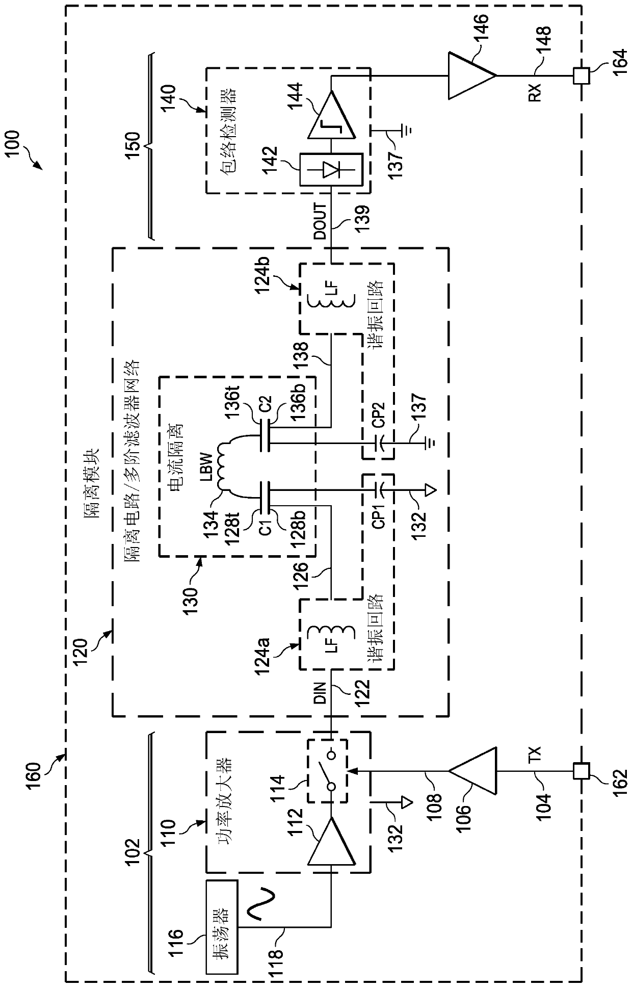
[0021] refer to figure 1 , the described example provides capacitive coupling isolation circuitry 120, system and filter circuitry. Examples include a capacitively coupled isolation circuit 130 having a first coupling capacitor C1 and a second coupling capacitor C2 connected by a bond wire 134, and a first circuit 124a and a second circuit 124b having an inductor LF to create a circuit with coupling Capacitors C1 and C2 are associated with parasitic capacitors ...


PUM


Abstract

In described examples, a digital isolator module (160) includes isolation circuitry (120). The isolation circuitry (120) includes a capacitive coupled galvanic isolation circuit (130) with first and second coupling capacitors (C1, C2) individually including a first plate (128t, 136t) and a second plate (128b, 136b), and a bond wire (134) connecting the first plates (128t, 136t). A first circuit (124a) has a first inductor (LF) coupled to form a first resonant tank circuit with a first parasitic capacitor (CP1) associated with the second plate (128b) of the first coupling capacitor (C1). A second circuit (124b) has a second inductor (LF) coupled to form a second resonant tank circuit with a second parasitic capacitor (CP2) associated with the second plate (136b) of the second coupling capacitor (C2).

Description

Background technique [0001] Isolation is often required for interconnected electrical systems that exchange data and power with each other. For example, two systems can be powered by different power supplies that do not share a common ground connection. Transformer isolation methods involve magnetic fields, and the resulting electromagnetic interference (EMI) may be undesirable in some applications. Additionally, transformer isolation often requires external transformer components, and these solutions require significant circuit or board area and are costly. Optical isolation avoids the EMI problems associated with transformer isolation. However, optical circuits are usually expensive and have limited speed. Capacitive coupling or AC coupling using capacitors connected in series can be used to provide isolation for the transmitted data signal. However, capacitor-based isolation solutions often involve parasitic capacitances that absorb signal energy and cause significant s...

Claims


Application Information

Patent Timeline
IPC IPC(8): H04B3/21
CPCH03H7/0115H03H7/0138H03H7/03H03H7/1708H03H7/175H03H7/1775H03H7/09H04L25/0266H04L25/0272H01L2224/48137H01L2224/49175
Inventor S·桑卡兰B·A·克莱默B·哈龙
Owner TEXAS INSTR INC
Why Eureka
Try Eureka