

Respirator with electron current
A ventilator with electronic technology, which is applied in the field of ventilators, can solve the problems of not knowing the electronic path, positioning, and not providing a negative ion circuit, so as to improve the function and promote the metabolism.
- Summary
- Abstract
- Description
- Claims
- Application Information
AI Technical Summary
Problems solved by technology
Method used
Image

Examples
Embodiment 1
[0023] Example 1: See Figure 1-7 , in order to achieve said purpose, the present invention provides following technical scheme:
[0024] A ventilator with electronic flow, comprising a pre-stage rectification filter module, a power conversion module, a post-stage rectification filter module, an output module, a voltage stabilization module, a current limiting protection module and a pulse width controller, the pre-stage rectification filter module The input voltage is processed and then transmitted to the power conversion module. The power conversion module converts the input voltage and outputs it to the post-stage rectification filter module. The post-stage rectification filter module outputs the voltage to the output module, and the output module supplies power to the mask, top plate and bottom plate respectively. , the output module is also connected to the pulse width controller, the voltage stabilizing circuit and the current limiting protection module, and the pulse wi...
Embodiment 2
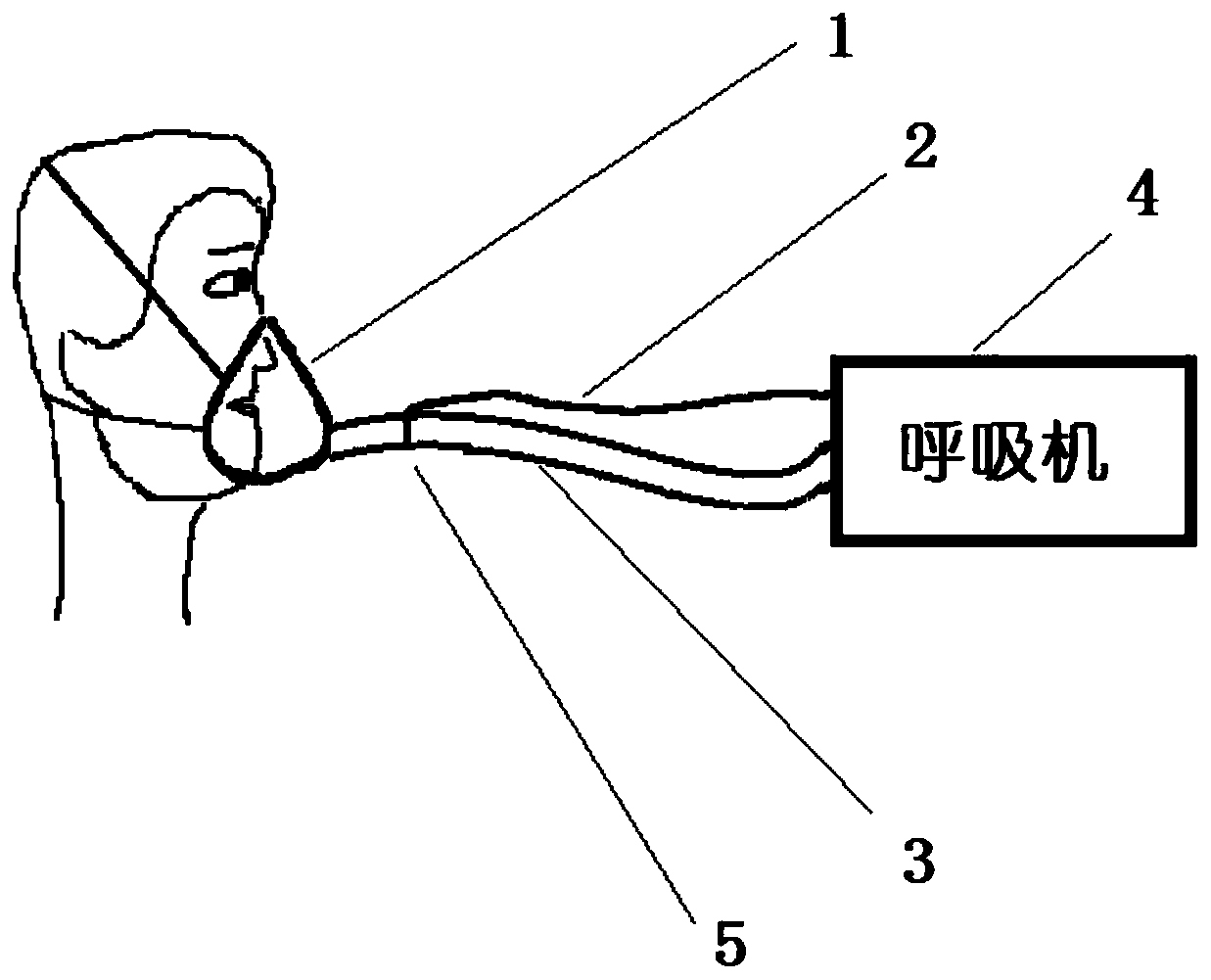
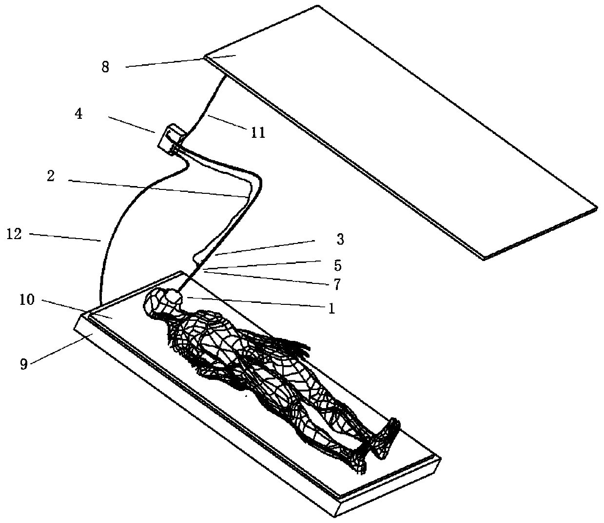
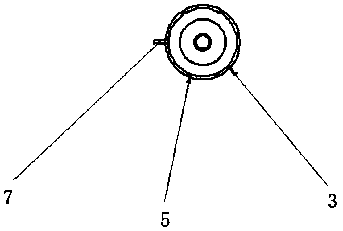
[0025] Embodiment 2, on the basis of embodiment 1, figure 2 A schematic diagram of the connection between the ventilator, conductive mesh and mask, and the external environment is depicted. Among them, 1 is a mask; 2 is a wire that provides electrons, which is rich in electrons (negative charge); 3 is a hose that provides air; 4 is a ventilator; 5 is a conductive mesh, made of conductive materials, and 5 is embedded in the air In the middle of the hose 3, so that electrons are released into the air, 7 is a conductive mesh interface to connect the conductive mesh 5 and the wire 2; 8 is the top, 9 is the bottom, and 8 and 9 are surfaces made of conductive materials, which can Have different potentials to produce the required strength; 10 is a mesh structure made of non-conductive material to support the subject, but allows electrons to pass through; 11 and 12 are wires with positive charges, 11 is connected to 8 , 12 is connected to 9 to provide a path for the electrons back t...
Embodiment 3
[0026] Embodiment 3, on the basis of embodiment 1 and 2, the circuit diagram that the electron produces is as Figure 5 As shown, it includes rectifier bridge BR1, PWM chip U1 and PWM chip U3. The input terminal of rectifier bridge BR1 is connected to AC power, and the output terminal is connected to the primary winding of transformer TR1 and primary winding of transformer TR2 after passing through filter capacitors C1 and C2. PWM chip U3 The pin 6 of the PWM chip U1 is connected to the base of the transistor Q1 through the resistor R3, the collector of the transistor Q1 is connected to the other end of the primary winding of the transformer TR1, the pin 6 of the PWM chip U1 is connected to the base of the transistor Q2 through the resistor R10, and the collector of the transistor Q2 is connected to the transformer On the other end of the primary winding of TR2, the rectifier bridge BR1 and capacitors C1 and C2 rectify and filter the input AC power to provide DC power for the s...
PUM
 Abstract
Description
Claims
Application Information