Grounding structure for electroplating decoration ring

A grounding structure and decorative ring technology, applied in the direction of conductive connection, upper structure, upper structure sub-assembly, etc., can solve the problems of touch screen flickering, easy coupling of driving PCB board, and no effect of touch, etc., to achieve enhanced anti-corrosion The effect of damage strength

Active Publication Date: 2019-11-19
HUIZHOU DESAY SV AUTOMOTIVE
View PDF5 Cites 2 Cited by
  • Summary
  • Abstract
  • Description
  • Claims
  • Application Information

AI Technical Summary

Problems solved by technology

[0007] The purpose of the present invention is to solve the problem that the existing electroplating decorative ring does not have any contact with other parts of the screen assembly. The screen on the center console is an exposed part. The surface of the electroplating decorative ring is attached with a metal conductive layer. When there is ESD static electricity, the electroplating decorative ring is easily coupled with the touch screen and the drive PCB board, resulting in bad problems such as flickering of the touch screen and no touch effect.

Method used


Image

  • Grounding structure for electroplating decoration ring
  • Grounding structure for electroplating decoration ring
  • Grounding structure for electroplating decoration ring

Examples


Embodiment 1

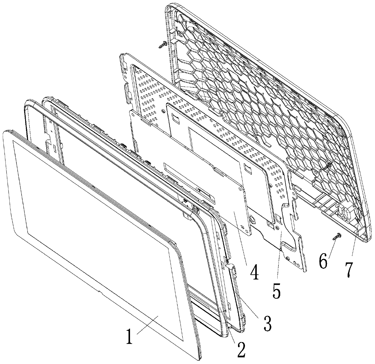
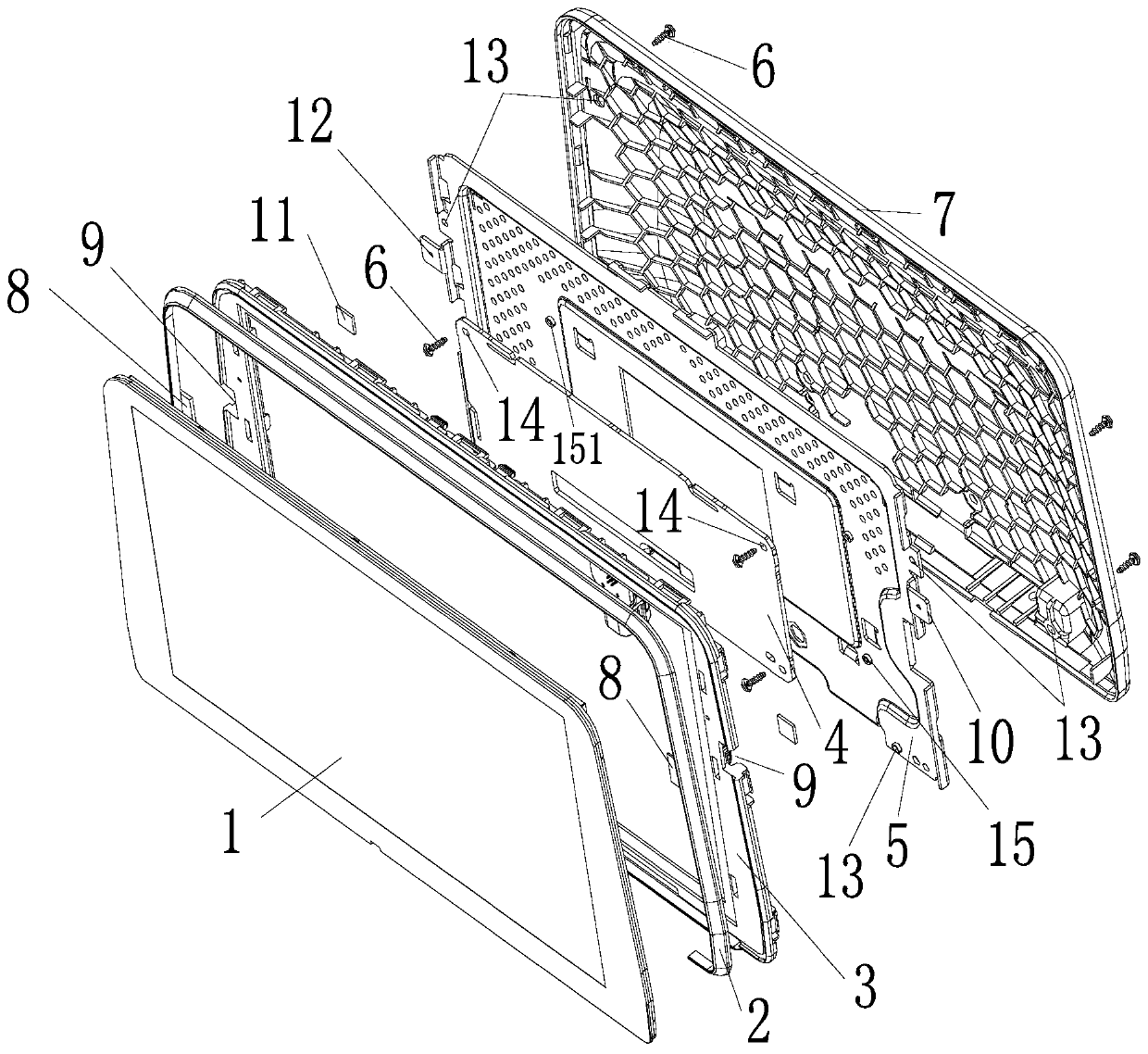
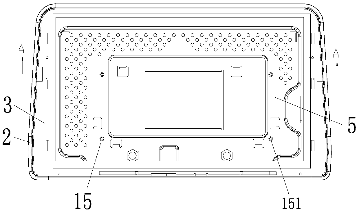
[0034] Such as Figures 2 to 5 As shown, a grounding structure of an electroplating decorative ring includes a plastic panel 3, an electroplating decorative ring 2 embedded in the outer surface of the plastic panel 3 through buckles or glue, and a driving PCB board 4 located on the back of the plastic panel 3, which is located at the driving The hardware bracket 5 on the back of the PCB board 4 locks the drive PCB board 4 to the front of the hardware bracket 5 through fixing parts such as four screws 6, and also includes a touch display screen 1 installed in front of the plastic panel 3, which is located on the back of the hardware bracket 5 The rear cover 7 is fastened to the back of the plastic panel 3 through fixing components such as four screws 6 passing through the second screw holes 13 of the rear cover 7 and the hardware bracket 5 respectively. At least two conductors 8 are arranged on the electroplating decoration ring 2, and the conductors 8 are arranged on both side...

Embodiment 2

[0041] Such as Figures 6 to 8 As shown, the difference from the above-mentioned embodiment 1 is that the conductor 8 is an elastic body 82 provided on the inner ring of the electroplated decoration ring 2 .

[0042] Furthermore, the elastic body 82 is preferably a curved structure, and the elastic body 82 can pass through the gap 9 on the plastic panel 3 , interfere with and electrically connect with the connecting body 10 provided on the hardware bracket 5 .

[0043] Further, both ends of the elastic body 82 are respectively provided with a right-angle bend, the right-angle bend at the front end is convenient to penetrate the gap 9, and the right-angle bend at the rear end is convenient to interfere with the connecting body 10, and the connecting body 10 is provided with a forward bending The mesa 101, the mesa 101 makes grounding easier and can resist the pressure of the elastic body 82 without deformation. The rest of the content is the same as that of Embodiment 1 and wi...

Embodiment 3

[0045] Such as Figures 9 to 11 As shown, different from the above-mentioned embodiment 2, the two ends of the elastic body 82 are perpendicular to each other, and its front end is connected to the electroplating decorative ring 2, and its rear end is in elastic contact with the outer surface of the forward straight part 102 of the connecting body 10 and For electrical connection, the interference of spring pressure is a, and the end of the contact surface between the straight extension part 102 and the rear end of the elastic body 82 is respectively provided with chamfers, which is convenient for assembly and electrical connection. The rest of the content is the same as that of Embodiment 2 and will not be repeated here.

[0046] In summary, adopting the technical solution of the present invention has the following beneficial effects:

[0047] The present invention solves the problem that the existing electroplating decorative ring does not have any contact with other parts ...


PUM


Abstract

The invention relates to a grounding structure for an electroplating decoration ring. The grounding structure comprises a plastic panel, the electroplating decoration ring which is embedded into the outer surface of the periphery of the plastic panel, a driving PCB located on the back side of the plastic panel and a hardware support located on the back side of the driving PCB. The driving PCB is locked onto the front side of the hardware support through a fixing part. The grounding structure further comprises a touch display screen installed on the front side of the plastic panel and a rear cover located on the back side of the hardware support. The rear cover and the hardware support are fastened onto the back side of the plastic panel through a fixing part. The electroplating decorationring is provided with two electric conductors, and the electric conductors penetrate through notches formed in the plastic panel and are further electrically connected with a connector arranged on thehardware support. A conductive circular ring is arranged on the back side of a first screw hole of the driving PCB. A conductive circular ring is arranged at the front end of a screw stud on the hardware support, and the conductive circular ring is electrically connected with the conductive circular ring of the first screw hole in the driving PCB. According to the grounding structure for the electroplating decoration ring, structural design is reasonable and practical, the reliability of products is improved and meanwhile assembling is made quite convenient.

Description

technical field [0001] The invention relates to the field of automotive interior parts, in particular to a grounding structure of an electroplated decorative ring. Background technique [0002] In the design of automotive interior parts, in order to pursue the metal texture, the electroplating process will be used in the interior parts. The car central control screen is a key part of the car interior parts. Customers will use electroplating decorative rings for the circumference of the central control screen , with a silver metallic decorative ring surrounding the black screen, the color matching appears to have a sense of hierarchy, which enhances the visual effect and improves the grade of the car interior parts. [0003] An existing structural scheme of an automobile center console screen component, such as figure 1 As shown, it generally consists of a touch screen 1, an electroplating decorative ring 2, a plastic panel 3, a drive PCB board 4, a hardware bracket 5, screw...

Claims


Application Information

Patent Timeline
Patent Type & Authority Applications(China)
IPC IPC(8): B60R16/06B60R13/02H01R4/64H01R4/30H01R4/48
CPCB60R16/06B60R13/02H01R4/64H01R4/30H01R4/4809H01R4/48B60R2013/0287H01R2201/26
Inventor 吴志党黄金章
Owner HUIZHOU DESAY SV AUTOMOTIVE
Why Eureka
Try Eureka